
Seat Ibiza (6F) 2017-2026 Owner's Manual: Tyre mobility system contents
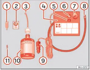
Fig. 191 Standard display: contents of the tyre
mobility system.
The Tyre Mobility System supplied with the Seat Ibiza is stored beneath the floor covering in the luggage compartment. This location keeps the repair equipment together and protected during normal vehicle use while allowing it to be accessed when a puncture occurs. To reach the kit, open the luggage compartment and lift the floor covering. Depending on the vehicle's equipment and luggage compartment arrangement, it may be necessary to move the floor panel or other stored items before the repair kit can be removed.
Before using the system, check that the required components are present and that the sealant bottle has not passed its expiry date. The compressor, hoses, electrical connector and valve accessories must be in suitable condition for use. Familiarising yourself with the equipment before an emergency can make the repair procedure easier to carry out safely. The exact appearance of some components may vary depending on the version of the Tyre Mobility System supplied with the vehicle.
The repair kit contains the following components, identified by the corresponding numbers in Fig. 191:
- Valve insert remover. This tool is used to remove and reinstall the valve insert from the tyre inflation valve when required by the sealing procedure. It is shaped to engage with the valve insert so that the component can be unscrewed without damaging the valve. Use the tool carefully and keep the removed insert in a clean, secure location until it is needed again.
- Maximum speed warning sticker. The kit includes an adhesive label displaying the recommended maximum speed of "max. 80 km/h" or "max. 50 mph". The sticker should be placed on the instrument cluster or another suitable location within the driver's field of view, as instructed, so that the speed restriction remains clearly visible while the temporarily repaired tyre is being used. It serves as a reminder that normal driving speeds must not be resumed until the damaged tyre has been replaced.
- Filler tube with cap. The filler tube is used to introduce the sealing compound from the bottle into the damaged tyre. Its cap protects the connection when the tube is not in use and helps keep the component clean during storage. The tube must be connected according to the repair kit manufacturer's instructions to ensure that the sealant is transferred correctly and unnecessary leakage is avoided.
- Air compressor. The electrically powered compressor is used to inflate the tyre during the temporary repair procedure. It provides the air pressure required after the sealing compound has been introduced. The compressor's external design and the arrangement of its controls may differ depending on the version supplied with the Seat Ibiza. Follow the operating instructions for the specific compressor included in your vehicle, particularly those concerning electrical connection and inflation.
- ON/OFF switch. This switch controls operation of the air compressor. Use it to start inflation once the equipment has been connected correctly and to stop the compressor when the required stage of the procedure has been completed. Before switching the compressor on, make sure that the hose and electrical connector are securely attached and that the equipment is positioned safely.
- Air bleed screw. The air release screw allows excess pressure to be reduced when necessary during tyre inflation. Depending on the compressor version, this function may be provided by a separate screw or integrated into the inflation tube assembly. Use the pressure release mechanism carefully and follow the manufacturer's instructions when adjusting the tyre pressure. Avoid releasing more air than necessary, as the tyre must remain inflated to the specified pressure.
- Tyre pressure monitoring or pressure indication component. The repair kit includes a means of checking the pressure during inflation. Depending on the equipment version, the pressure indication may be integrated into the inflator tube or compressor assembly. This component allows the user to monitor the tyre's inflation pressure and determine whether the required value has been reached. The pressure must also be checked again after the initial period of driving to assess the effectiveness of the temporary seal.
- Tyre inflation hose. This hose connects the air compressor to the tyre valve and carries compressed air into the tyre. The connection must be fitted securely to minimise air leakage during inflation. Inspect the hose for visible damage before use, and avoid sharp bends or excessive tension that could interfere with airflow or damage the connection. After the procedure, disconnect it carefully and return it to its storage position.
- 12-volt electrical connector. The compressor is supplied with a connector intended for the vehicle's 12-volt electrical system. This provides the power required to operate the compressor during the repair procedure. Connect it only as specified in the equipment manufacturer's instructions. Make sure that the connector is correctly inserted and that the cable is routed where it cannot become trapped, damaged or stretched while the compressor is operating.
- Tyre sealant bottle. The bottle contains the sealing compound used to close suitable small punctures temporarily. Its contents are intended for the specific repair procedure described by the Tyre Mobility System manufacturer. Check the expiry date before use and do not use the sealant if the bottle is expired or damaged. Once the sealant has been used, arrange for a compatible replacement bottle so that the repair kit remains complete.
- Spare tyre valve insert. A replacement valve insert is supplied in case the original insert needs to be replaced during the repair procedure. The replacement component must be handled carefully to prevent contamination or damage to its sealing surfaces. Install it using the appropriate valve insert remover and follow the instructions supplied with the kit. A correctly installed valve insert is necessary to maintain tyre pressure after inflation.
The valve insert remover, identified as component 1 in Fig. 191, has a specially shaped opening at its lower end that fits the tyre valve insert. This opening allows the insert to be engaged and turned so that it can be unscrewed from or screwed into the valve correctly. The same tool is used when installing the replacement valve insert identified as component 11. The valve insert is a small but essential part of the tyre inflation system, as it controls airflow through the valve and helps retain pressure inside the tyre. Handle it carefully, keep it free from dirt and make sure it is correctly seated when refitted. Do not attempt to remove or install the insert using unsuitable tools that could damage the valve or prevent it from sealing properly.
 TMS (Tyre Mobility System) puncture
repair kit
The Tyre Mobility System (TMS) supplied with the Seat Ibiza is designed to provide a temporary solution for
certain tyre punctures without requiring an immediate wheel change. The repair kit can eff ...
 Sealing and inflating a tyre
Sealing the tyre
Unscrew the protective cap from the valve of the damaged tyre. Next, use the valve insert remover supplied
with the Tyre Mobility System, identified as component 1 in Fig. 19 ...
See also:
Honda Civic Service Manual. Rear Seat-Back Removal and Installation - Split Fold Down type (4-door)
Removal
1.
Right Rear Seat-Back - Split Fold Down
1.
Remove the right rear seat-back (A).
2.
Center Pivot Bracket - Split Fold Down
...
