Honda Civic Service Manual: Fuel Pump/Fuel Gauge Sending Unit Removal and Installation (R18Z1)

Removal
|
|
1.
|
Remove the fuel fill cap to relieve the pressure in the fuel
tank.
|
|
|

|
|
NOTE: For specific operations, refer to the user's manual that
came with the Honda Diagnostic System (HDS). Make sure the HDS is
loaded with the latest software.
|
|
1.
|
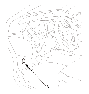
Connect the HDS to the data link connector (DLC) (A) located
under the driver's side of the dashboard.
|
|
2.
|
Turn the ignition switch to ON (II).
|
|
3.
|
Make sure the HDS communicates with the vehicle. If it does not
communicate, go to the DLC circuit troubleshooting.
|
|
|
|
1.
|
Turn the ignition switch to ON (II).
|
|
2.
|
From the INSPECTION MENU of the HDS, select Fuel Pump OFF, then
start the engine, and let it idle until it stalls.
|
|
NOTE:
|
|

|
Do not allow the engine to idle above 1,000 rpm
or the ECM/PCM will continue to operate the fuel
pump.
|
|
|
|
Pending or Confirmed DTC may be set during this
procedure. Check for DTCs, and clear them as needed.
|
|
|
|
3.
|
Turn the ignition switch to LOCK (0).
|
|
| 4. |
Battery Terminal - Disconnection |
|
|
|
1.
|
Make sure the ignition switch is in LOCK (0).
|
|
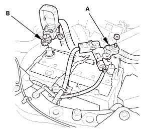
2.
|
Disconnect and isolate the negative cable and battery sensor
(A) from the battery.
|
|
NOTE: Always disconnect the negative side first.
|
|
3.
|
Disconnect the positive cable (B) from the battery.
|
|
| 5. |
Fuel Pressure - Relieving |
|
|
|
1.
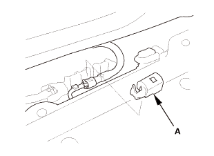
|
Remove the quick-connect fitting cover (A).
|
|
2.
|
Check the fuel quick-connect fitting for dirt, and clean it if
needed.
|
|
|
|
|
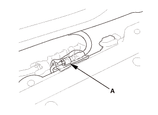
3.
|
Place a rag or shop towel over the quick-connect fitting (A).
|
|
|
|
|
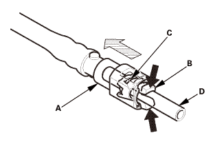
4.
|
Disconnect the quick-connect fitting: Hold the connector (A)
with one hand, and squeeze the retainer tabs (B) with the other
hand to release them from the locking tabs (C). Pull the connector
off.
|
|
NOTE:
|
|
|
Be careful not to damage the line (D) or other
parts.
|
|
|
|
Do not use tools.
|
|
|
|
If the connector does not move, keep the retainer
tabs pressed down, and alternately pull and push
the connector until it comes off easily.
|
|
|
|
Do not remove the retainer from the line; once
removed, the retainer must be replaced with a new
one.
|
|
|
|
|
|
|
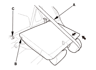
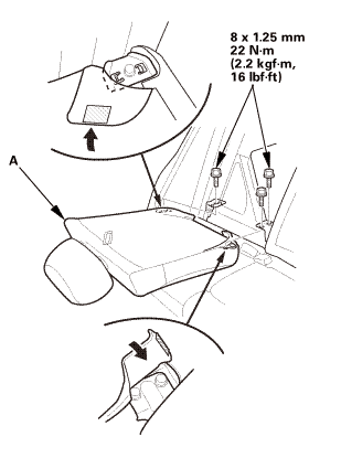
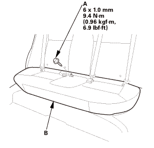
1.
|
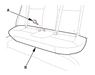
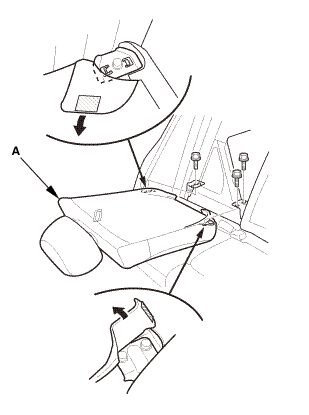
Remove the bolt (A) securing the rear seat cushion (B).
|
|
|
|
|
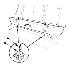
2.
|
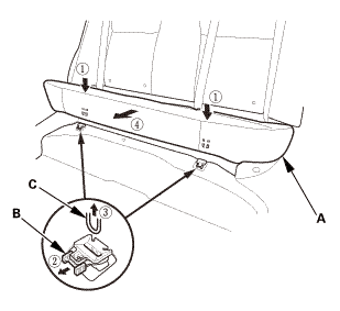
While pushing down the rear seat cushion (A), pull the seat hook
handles (B) to release the hooks (C).
|
|
3.
|
Remove the rear seat cushion.
|
|
|
|
|
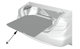
1.
|
Fold down the seat-back(s).
|
|
2.
|
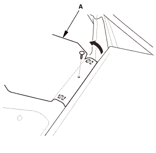
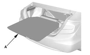
Remove the front area of the trunk floor cover (A).
|
|
|
|
|
3.
|
Remove the trunk floor cover (A).
|
|
| 8. |
Right Rear Seat-Back - Split Fold Down |
|
|
|
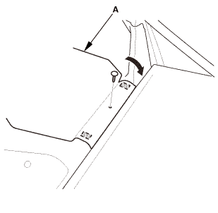
1.
|
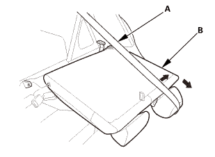
Remove the right rear seat-back (A).
|
|
| 9. |
Center Pivot Bracket - Split Fold Down |
|
|
|
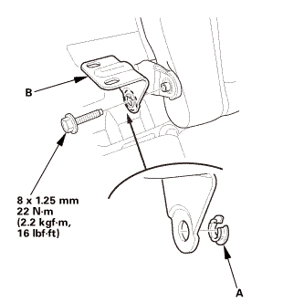
1.
|
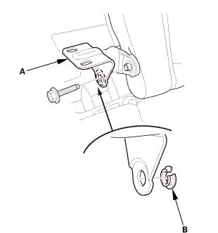
Remove the center pivot bracket (A).
|
|
2.
|
If necessary, remove the bushing (B).
|
|
| 10. |
Left Rear Seat-Back - Split Fold Down |
|
|
|
1.
|
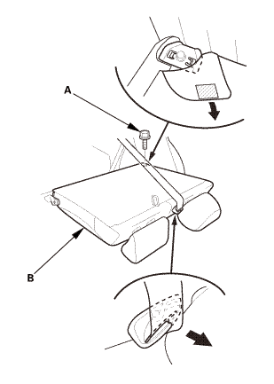
Remove the bolt (A) securing the left rear seat-back (B).
|
|
|
|
|
2.
|
Extend the center seat belt (A), then remove the left rear seat-back
(B).
|
|
| 11. |
Rear Floor Upper Cross-Member |
|
|
|
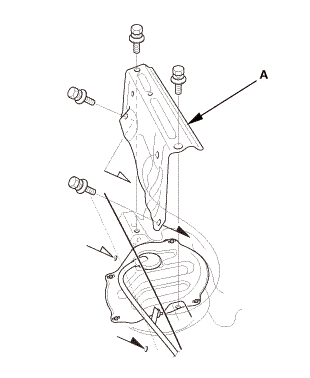
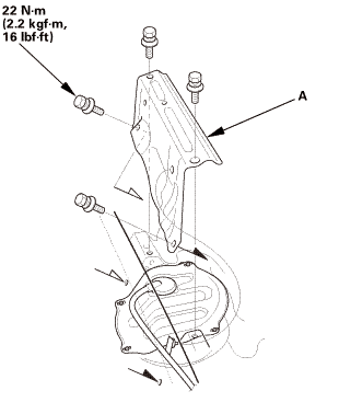
1.
|
Remove the rear floor upper cross-member (A).
|
|
| 12. |
Fuel Gauge Sending Unit Access Panel |
|
|
|
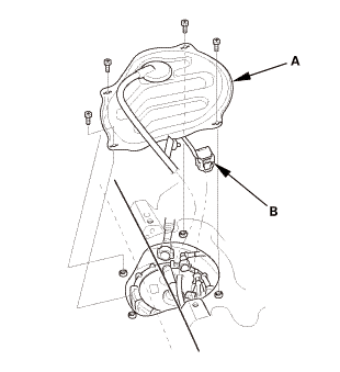
1.
|
Remove the access panel (A) from the floor.
|
|
2.
|
Disconnect the connector (B).
|
|
|
|
|
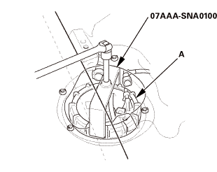
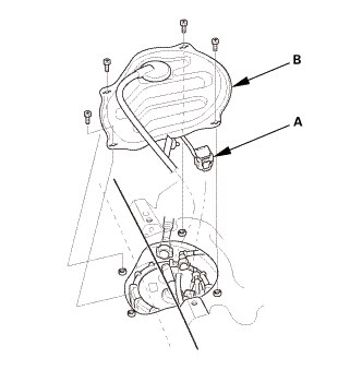
1.
|
Using the special tool, loosen the locknut (A).
|
|
|
|
|
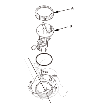
2.
|
Remove the locknut (A).
|
|
3.
|
Remove the fuel tank unit (B).
|
|
| 14. |
Fuel Gauge Sending Unit |
|
|
|
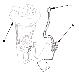
1.
|
Remove the fuel level sensor (fuel gauge sending unit) (A) from
the fuel tank unit (B).
|
|
2.
|
Check these items before installing the fuel tank unit:
|
|
|
When connecting the wire harness, make sure the
connection is secure and the connector (C) is firmly
locked into place.
|
|
|
|
When installing the fuel gauge sending unit,
make sure the connection is secure. Be careful not
to bend or twist it excessively.
|
|
|
|

Installation
| 1. |
Fuel Gauge Sending Unit |
|
|
|
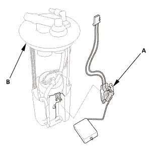
1.
|
Install the fuel level sensor (fuel gauge sending unit) (A) to
the fuel tank unit (B).
|
|
|
|
|
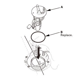
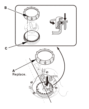
1.
|
Insert the fuel tank unit (A) into the fuel tank with a new O-ring
(B).
|
|
|
|
|
2.
|
Align the marks (A) on the fuel tank and the fuel tank unit,
then insert the fuel tank unit into the fuel tank.
|
|
NOTE: To prevent a fuel leak, check the base gasket, visually
or by hand, to make sure it is not pinched.
|
|
|
|
|
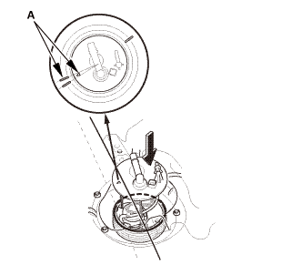
3.
|
Tighten a new locknut (A) by hand holding the fuel tank unit
vertically.
|
|
NOTE: Before tightening, align the mark (B) on the locknut to
the start of the thread (C).
|
|
|
 a7aaa.suaa1aa a7aaa.suaa1aa
|
|
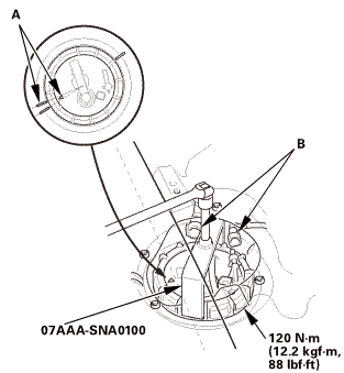
4.
|
Using the special tool, tighten the locknut to the specified
torque.
|
|
NOTE:
|
|
|
After tightening, make sure the marks (A) are
still aligned.
|
|
|
|
After installation, check the base gasket, visually
or by hand, to make sure it is not pinched.
|
|
|
|
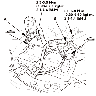
5.
|
Reconnect the quick-connect fittings (B).
|
|
| 3. |
Battery Terminal - Reconnection |
|
|
|
NOTE: If the battery performs abnormally, test the battery.
|
|
1.
|
Clean the battery terminals.
|
|
2.
|
Connect the positive cable (A) to the battery.
|
|
NOTE: Always connect the positive side first.
|
|
3.
|
Connect the negative cable and battery sensor (B) to the battery.
|
|
4.
|
Apply multipurpose grease to the terminals to prevent corrosion.
|
|
|
|
|
1.
|
Connect the HDS to the data link connector (DLC) (A) located
under the driver's side of the dashboard.
|
|
2.
|
Turn the ignition switch to ON (II).
|
|
3.
|
Make sure the HDS communicates with the vehicle. If it does not
communicate, go to the DLC circuit troubleshooting.
|
|
|
|
1.
|
From the INSPECTION MENU of the HDS, select Fuel Pump ON.
|
|
NOTE: Pending or Confirmed DTC may be set during this procedure.
Check for DTCs, and clear them as needed.
|
|
2.
|
Turn the ignition switch to LOCK (0).
|
|
| 6. |
Fuel Gauge Sending Unit Access Panel |
|
|
|
1.
|
Connect the connector (A).
|
|
2.
|
Install the access panel (B) to the floor.
|
|
|
|
1.
|
Turn the ignition switch to ON (II) (but do not operate the starter
motor). The fuel pump runs for about 2 seconds, and fuel pressure
rises. Repeat this two or three times, then make sure there are
no fuel leaks.
|
|
| 8. |
Rear Floor Upper Cross-Member |
|
 22mm 22mm
|
|
1.
|
Install the rear floor upper cross-member (A).
|
|
| 9. |
Left Rear Seat-Back - Split Fold Down |
|
|
|
1.
|
Extend the center seat belt (A), then install the pivot shaft
(B) to the center pivot bracket (C).
|
|
|
|
|
2.
|
Install the left rear seat-back (A).
|
|
| 10. |
Center Pivot Bracket - Split Fold Down |
|
|
|
1.
|
If necessary, install the bushing (A).
|
|
2.
|
Install the center pivot bracket (B).
|
|
| 11. |
Right Rear Seat-Back - Split Fold Down |
|
|
|
1.
|
Install the right rear seat-back (A).
|
|
|
|
1.
|
Install the fuel fill cap.
|
|
|
|
|
1.
|
Install the trunk floor cover (A).
|
|
|
|
|
2.
|
Install the front area of the trunk floor cover (A).
|
|
3.
|
Raise the seat-back(s).
|
|
|
|
|
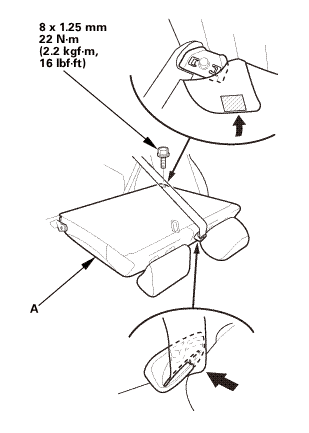
1.
|
Install the hooks (A) to the rear seat cushion clips (B).
|
|
|
|
|
2.
|
Install the bolt (A) securing the rear seat cushion (B).
|
|
1.
HDS DLC - Connection
NOTE: For specific operations, refer to the user's manual that
came with the Honda Diagnostic Sy ...
1.
HDS DLC - Connection
NOTE: For specific operations, refer to the user's manual that
came with the Honda Diagnostic Sy ...
 Rewriting the ODO Data and Transferring the Maintenance Minder™ Data to a New
Gauge Control Module ('13)
Rewriting the ODO Data and Transferring the Maintenance Minder™ Data to a New
Gauge Control Module ('13) Rewriting the ODO Data and Transferring the Maintenance Minder™ Data to a New
Gauge Control Module ('13)
Rewriting the ODO Data and Transferring the Maintenance Minder™ Data to a New
Gauge Control Module ('13)