Honda Civic Service Manual: Side Impact Sensor (First) Removal and Installation (4-door)
7521B6 LEFT FRONT
7521B7 RIGHT FRONT

|
NOTE: SRS components are located in this area. Review the SRS component
locations and the precautions and procedures before doing repairs or service.
|
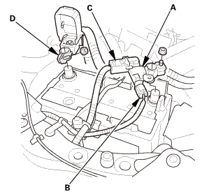
| 1. |
Battery Terminal (SRS) - Disconnection |
|
|
|
1.
|
Make sure the ignition switch is in LOCK (0).
|
|
2.
|
Disconnect and isolate the negative cable with the battery sensor
(A) from the battery.
|
|
NOTE:
|
|

|
Always disconnect the negative side first.
|
|
|
|
To protect the battery sensor connector (B) from
damage, do not hold it when removing the negative
terminal.
|
|
|
|
Do not disconnect the battery sensor from the
negative terminal (C).
|
|
|
|
3.
|
Disconnect the positive cable (D) from the battery.
|
|
4.
|
Wait at least 3 minutes before starting work.
|
|
|

|
|
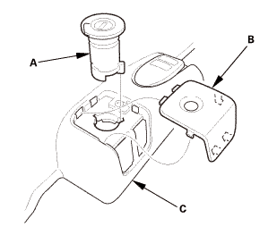
1.
|
Driver's side: Remove the cap (A) from the front door sill trim
(B).
|
|
2.
|
Driver's side: Remove the opener lock cylinder (C).
|
|
|
|
|
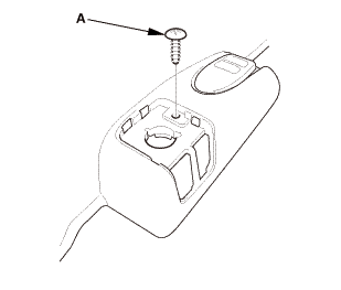
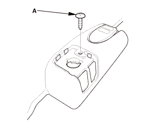
3.
|
Driver's side: Remove the screw (A).
|
|
|
Driver's side
Passenger's side

|
|
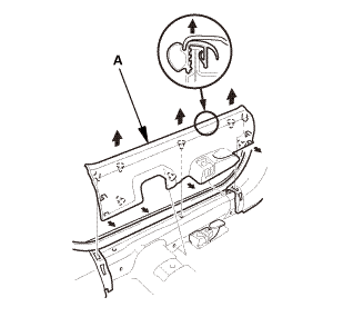
4.
|
Remove the front door sill trim (A).
|
|
|
|
|
1.
|
While pushing down on the rear seat cushion (A), pull the seat
hook handle (B) to release the hook (C).
|
|
2.
|
While pulling up the seat cushion, remove the rear door sill
trim (D).
|
|
| 4. |
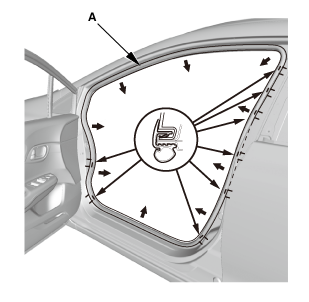
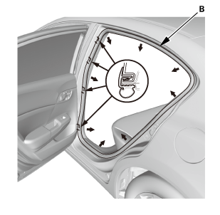
Front and Rear Door Opening Seals as Needed |
|
Front
Rear
|
|
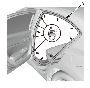
1.
|
Remove the front door opening seal (A) and the rear door opening
seal (B) as needed.
|
|
|
|
|
1.
|
Slide the front seat forward fully.
|
|
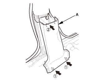
2.
|
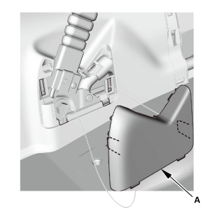
13-14 Models (driver's side): Remove the B-pillar lower cover
(A).
|
|
|
12 Model
13-14 Models
|
|
3.
|
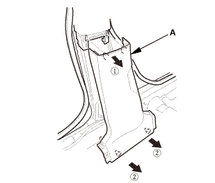
Remove the B-pillar lower trim (A).
|
|
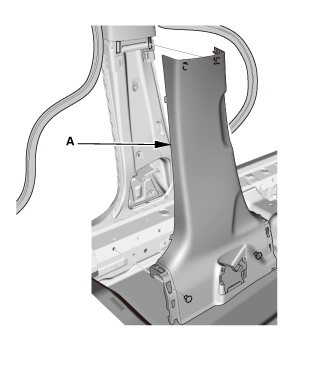
| 6. |
Side Impact Sensor (First) |
|
|
|
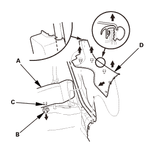
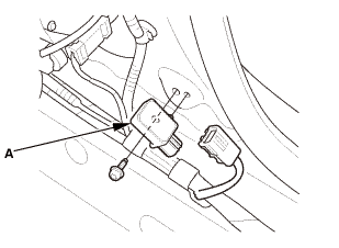
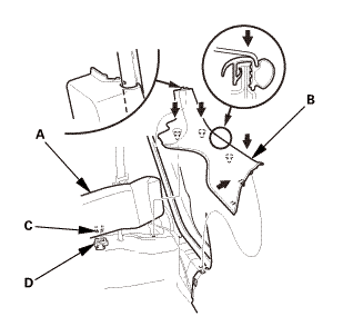
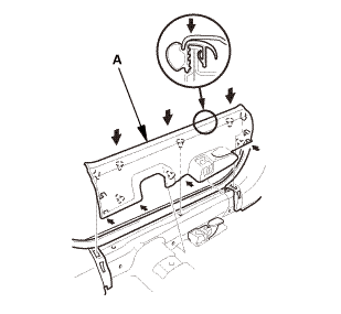
1.
|
Disconnect the side impact sensor (first) connector on the floor
wire harness.
|
|
2.
|
Remove the TORX bolt using a TORX T30 bit, then remove the side
impact sensor (first) (A).
|
|

|
NOTE: SRS components are located in this area. Review the SRS component
locations and the precautions and procedures before doing repairs or service.
|
| 1. |
Side Impact Sensor (First) |
|
|
|
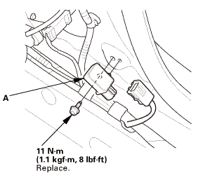
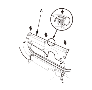
1.
|
Install the side impact sensor (first) (A) with the new TORX
bolt using a TORX T30 bit.
|
|
2.
|
Connect the side impact sensor (first) connector on the floor
wire harness.
|
|
| 2. |
Battery Terminal (SRS) - Reconnection |
|
 (o.2ao.sam. (o.2ao.sam.
|
|
NOTE: If the battery performs abnormally, test the battery.
|
|
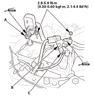
1.
|
Clean the battery terminals.
|
|
2.
|
Connect the positive cable (A) to the battery.
|
|
NOTE: Always connect the positive side first.
|
|
3.
|
Connect the negative cable and the battery sensor (B) to the
battery.
|
|
NOTE: To protect the battery sensor connector (C) from damage,
do not hold it when installing the negative terminal.
|
|
4.
|
Apply multipurpose grease to the terminals to prevent corrosion.
|
|
|
|
|
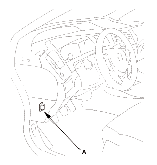
1.
|
Connect the HDS to the data link connector (DLC) (A) located
under the driver's side of the dashboard.
|
|
2.
|
Turn the ignition switch to ON (II).
|
|
3.
|
Make sure the HDS communicates with the vehicle. If it does not
communicate, go to the DLC circuit troubleshooting.
|
|
|
|
1.
|
Clear the DTC(s) by following the screen prompts on the HDS.
|
|
2.
|
Turn the ignition switch to LOCK (0), then wait for 10 seconds.
|
|
| 5. |
Confirm Proper SRS Operation |
|
|
Turn the ignition switch to ON (II), and check that the SRS indicator
comes on for about 6 seconds and then goes off.
|
|
|
12 Model
13-14 Models
|
|
1.
|
Install the B-pillar lower trim (A).
|
|
|
|
|
2.
|
13-14 Models (driver's side): Install the B-pillar lower cover
(A).
|
|
| 7. |
Front and Rear Door Opening Seals as Needed |
|
Front

Rear
|
|
1.
|
Install the front door opening seal (A) and the rear door opening
seal (B).
|
|
|
|
|
1.
|
While pulling up the rear seat cushion (A), install the rear
door sill trim (B).
|
|
2.
|
Push down the seat cushion, then install the hook (C) to the
rear seat cushion clip (D).
|
|
|
Driver's side
Passenger's side
|
|
1.
|
Install the front door sill trim (A).
|
|
|
|
|
2.
|
Driver's side: Install the screw (A).
|
|
|
|
|
3.
|
Driver's side: Install the opener lock cylinder (A).
|
|
4.
|
Driver's side: Install the cap (B) to the front door sill trim
(C).
|
|
7521B6 LEFT FRONT
7521B7 RIGHT FRONT
Removal
NOTE: SRS components are located in this area. Review the SRS component
locations and the precautions and procedures before doing re ...
7521C3 LEFT REAR
7521C4 RIGHT REAR
Removal
NOTE: SRS components are located in this area. Review the SRS component
locations and the precautions and procedures before doing repa ...
 Side Impact Sensor (First) Removal and Installation (2-door)
 Side Impact Sensor (Second) Removal and Installation (2-door)