Honda Civic Service Manual: M/T Mainshaft Assembly Clearance Inspection (R18Z1 M/T)
 Disassembly
| 1. | M/T Change Lever Assembly |
|
|
|
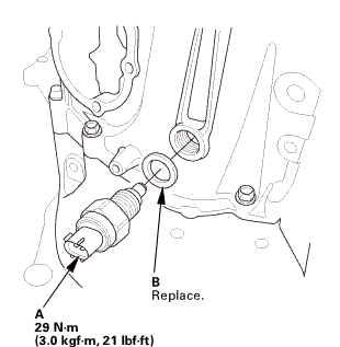
| 2. | Back Up Light Switch |
|
|
|
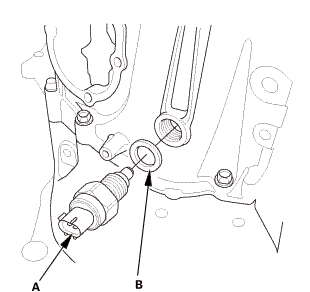
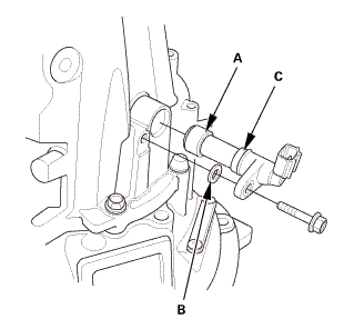
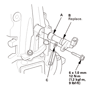
| 3. | M/T Output Shaft Speed Sensor |
|
|
|
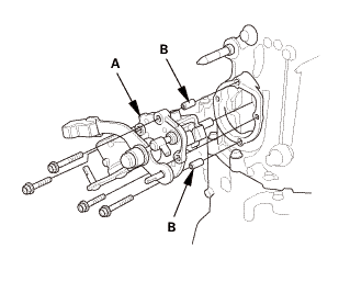
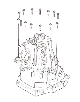
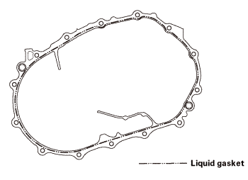
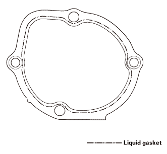
| 4. | M/T Transmission Housing Assembly |
|
|
|
|
|
|
|
|
|
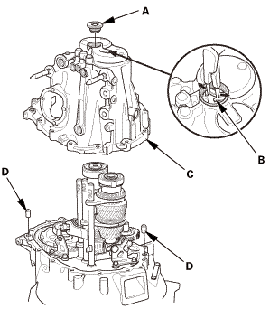
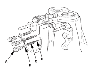
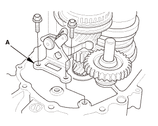
| 5. | M/T Reverse Shift Fork |
|
|
|
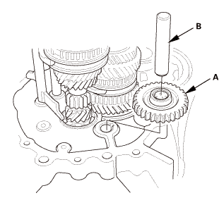
| 6. | Reverse Idler Gear |
|
|
|
| 7. | M/T Mainshaft and Countershaft and Shift Fork Assembly |
|
|
|
|||||||||||||||
 Inspection
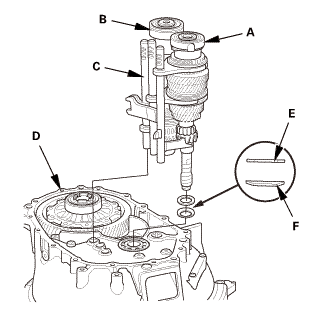
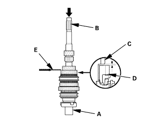
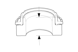
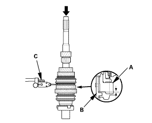
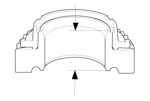
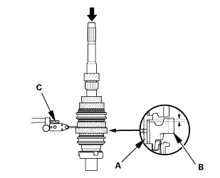
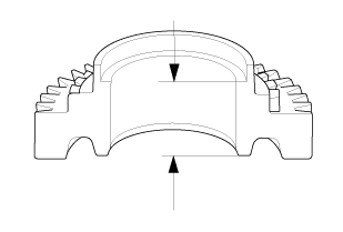
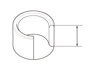
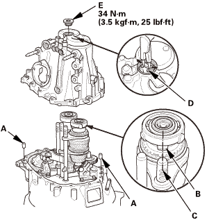
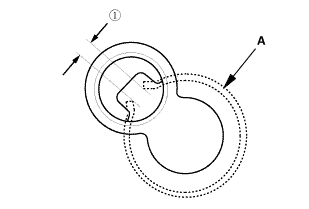
| 1. | Mainshaft Assembly Clearance Inspection |
|
|
|
||||||||||||||||||||||||||

|
|
|
|||||||||||||||||||||||
|
|
|
|||||||||||||||||||||||
|
|
|
|||||||||||||||||||||
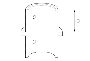
 of the 4th/5th
gear distance collar as shown.
of the 4th/5th
gear distance collar as shown.|
|
|
|||||||||||||||||||||||
|
|
|
|||||||||||||||||||||||
|
|
|
|||||||||||||||||||||
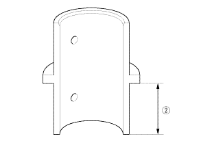
 of the 4th/5th
gear distance collar as shown.
of the 4th/5th
gear distance collar as shown.|
|
|
|||||||||||||||||||||||
|
|
|
|||||||||||||
 Reassembly
| 1. | M/T Mainshaft and Countershaft and Shift Fork Assembly |
|
|
|
||||||||||||||||||
| 2. | Reverse Idler Gear |
|
|
|
| 3. | M/T Reverse Shift Fork |
|
|
|
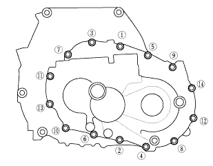
| 4. | M/T Transmission Housing Assembly |
|
|
|
||||||||||||||||||||
|
|
|
||||||||||||||||||
 imto
imto|
|
|
|||||||||||||||||||||||
|
|
|
|
|
|
||||||||||
|
|
|
 2215
2215| 5. | M/T Output Shaft Speed Sensor |
|
|
|
| 6. | Back Up Light Switch |
|
|
|
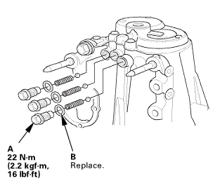
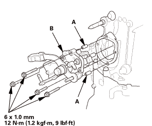
| 7. | M/T Change Lever Assembly |
|
|
|
||||||||||||||||||||
 -mid
-mid|
|
|
 .omm-m(i.2kvf-m.9bm1!
 M/T Mainshaft Assembly Clearance Inspection (K24Z7)
Removal
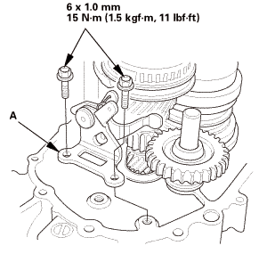
1.
M/T Change Lever Assembly
1.
Remove the interlock bolt (A).
...
 M/T Mainshaft Bearing and Oil Seal Replacement (R18Z1 M/T)
Removal
1.
M/T Change Lever Assembly
1.
Remove the change lever assembly (A).
...
See also:
Honda Civic Service Manual. Camshaft Removal and Installation (K24Z7)
1.
Air Cleaner Assembly
1.
Disconnect the intake air duct (A) and the intake air pipe (B).
2.
Remove the harness clamp (C).
...
