Honda Civic Service Manual: Clutch Master Cylinder Removal and Installation (K24Z7)
2111C5

|
NOTE: |
|
|||
|
|||
|
|||
|

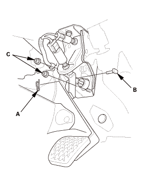
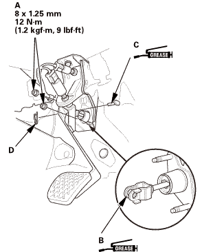
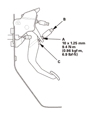
| 1. | Clutch Pedal |
|
|
|
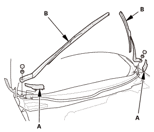
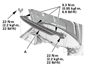
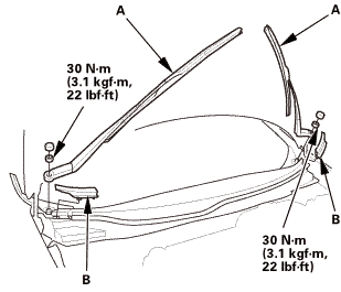
| 2. | Wiper Arm Assembly |
|
|
|
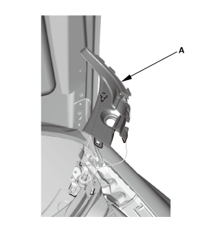
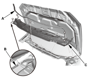
| 3. | Both Side Cowl Covers |
|
|
|
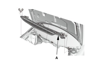
| 4. | Center Cowl Cover |
|
|
|

| 5. | Under Cowl Panel |
|
|
|
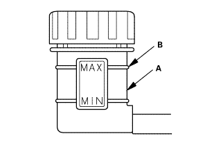
| 6. | Clutch Fluid |
|
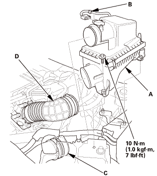
| 7. | Air Cleaner Assembly |
|
|
|
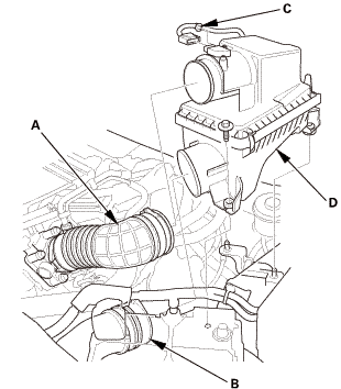
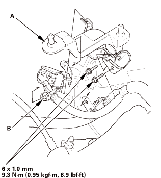
| 8. | Air Cleaner Bracket |
|
|
|
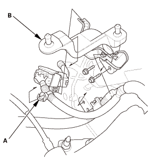
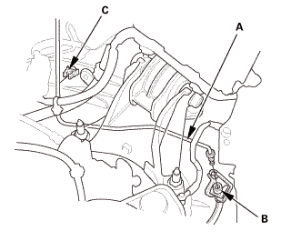
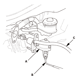
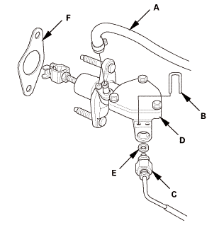
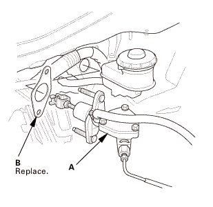
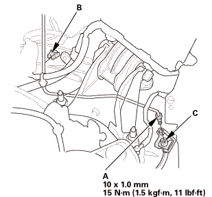
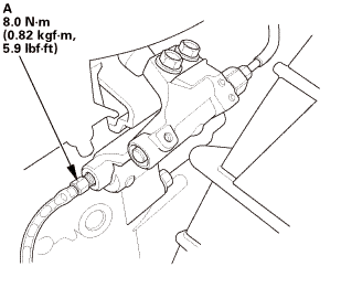
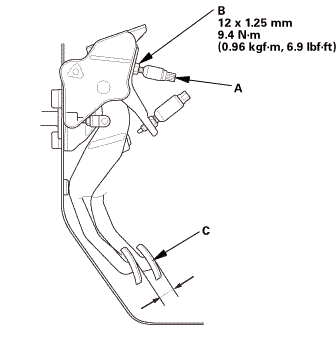
| 9. | Clutch Master Cylinder |
|
|
|
|
|
|
|
|
|
|||||||||||||||

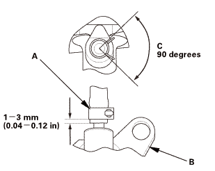
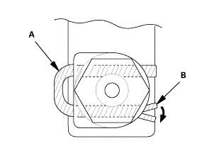
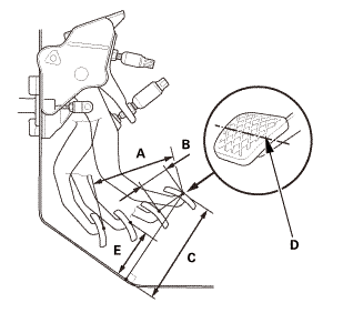
| 1. | Clutch Master Cylinder Push Rod Inspection |
|
|
|
||||||
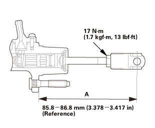 17inasmm
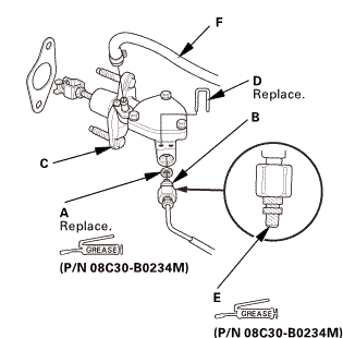
| 2. | Clutch Master Cylinder |
|
|
|
|||||||||||||||||||||||
|
|
|
||||||
 mm
mm|
|
|
|
|
|
|
|
|
| 3. | Clutch Pedal |
|
|
|
||||||||||||||||||
| 4. | Clutch Fluid |
|
| 5. | Clutch Fluid Bleeding (K24Z7 Engine) |
|
|
|
|
|
|
|||||||||||||||||||||||||||||||||
| 6. | Air Cleaner Bracket |
|
|
|
| 7. | Air Cleaner Assembly |
|
|
|
| 8. | Under Cowl Panel |
|
|
|
 22mm)2222
| 9. | Center Cowl Cover |
|
|
|
| 10. | Both Side Cowl Covers |
|
|
|
| 11. | Wiper Arm Assembly |
|
|
|
 1.122
1.122| 12. | Clutch Pedal Stroke Check |
|
|
|
|
|
|
||||||||||||||||||||||||||||||||||||
| 13. | HDS DLC - Connection |
|
|
|
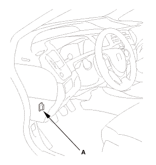
| 14. | Clutch Pedal Position Switch A Adjustment |
|
|
|
||||||||||||||||||||||||
| 15. | Clutch Operation Check |
|
| 16. | Test Drive |
|
 Clutch Disc Removal, Installation, and Inspection (R18Z1 M/T)
210105
Removal
1.
Pressure Plate
1.
Install the ring gear holder.
...
 Clutch Master Cylinder Removal and Installation (R18Z1 M/T)
211101
NOTE:
Use fender covers to avoid damaging painted surfaces.
...
See also:
Honda Civic Service Manual. Front Splash Guard Removal and Installation
0311A0 LEFT FRONT
031101 RIGHT FRONT
Removal
1.
Front Splash Guard
1.
...
