Honda Civic Service Manual: Alternator Overhaul (Except K24Z7)
 View
View
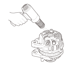
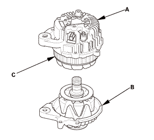
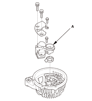
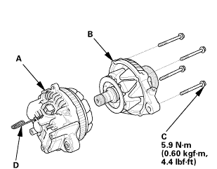
| 1. | Alternator Exploded View |
|
Exploded View |
 fnommsuuronvolrageassemelv
 Disassembly
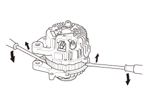
|
NOTE: Refer to the Exploded View if needed during this procedure. |
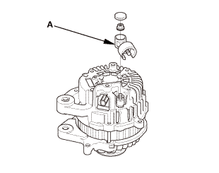
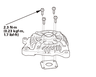
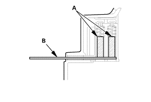
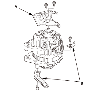
| 1. | Alternator Heat Shield |
|
|
|

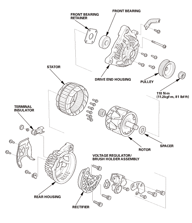
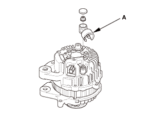
| 2. | Alternator Terminal Insulator |
|
|
|
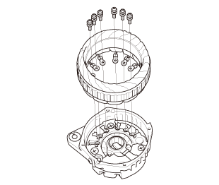
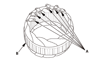
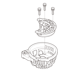
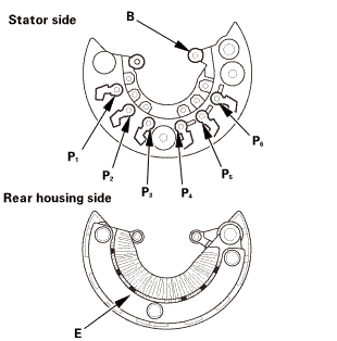
| 3. | Stator (Alternator) |
|
|
|
|
|
|
|
|
|
||||||
|
|
|
| 4. | Alternator Stator |
|
|
|
| 5. | Alternator Stator - Inspection |
|
|
|
||||||||||||
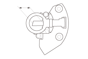
| 6. | Alternator Regulator |
|
|
|
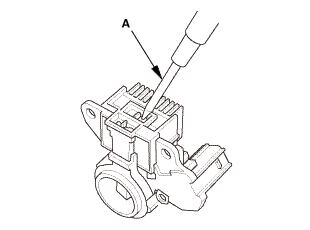
| 7. | Alternator Brush - Inspection |
|
|
|
|||||||||||||||||
|
|
|
| 8. | Rectifier |
|
|
|
| 9. | Rectifier - Inspection |
|
|
|
||||||
 sum!
sum!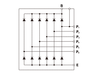
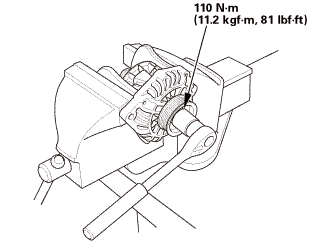
| 10. | Alternator Pulley |
|
|
|
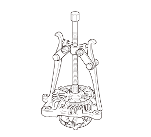
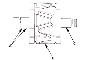
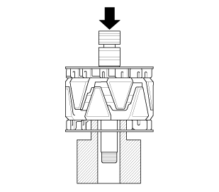
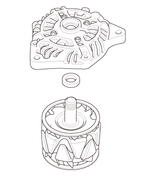
| 11. | Rotor (Alternator) |
|
|
|
|||||||||
| 12. | Alternator Rotor Slip Ring - Test |
|
|
|
|||||||||||||||||||||
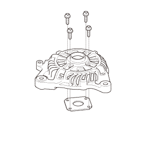
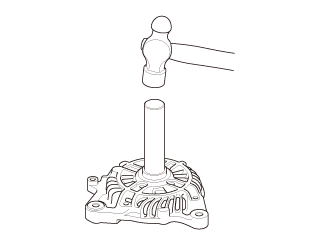
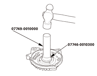
| 13. | Alternator Rear Bearing |
|
|
|

| 14. | Alternator Bearing Front |
|
|
|
|
|
|
 Reassembly
|
NOTE: Refer to the Exploded View if needed during this procedure. |
| 1. | Alternator Bearing Front |
|
|
|
|
|
|
| 2. | Alternator Rear Bearing |
|
|
|
| 3. | Rotor (Alternator) |
|
|
|
|
|
|
| 4. | Rectifier |
|
|
|
| 5. | Alternator Regulator |
|
|
|
| 6. | Alternator Stator |
|
|
|
| 7. | Stator (Alternator) |
|
|
|
|
|
|
| 8. | Alternator Terminal Insulator |
|
|
|
| 9. | Alternator Heat Shield |
|
|
|
 Charging
...
 Alternator Overhaul (K24Z7)
View
1.
Alternator Exploded View
Exploded View
frontsunhousinglocknuy.-nummholderassemblvrotorsun
Disassembly
NOTE: Refer to the Explode ...
See also:
Honda Civic Owners Manual. Getting Ready to Replace the Flat Tire
Open the trunk floor lid.
Take the tool case out of the trunk. Take
the jack and wheel nut wrench out of the
tool case.
Unscrew the wing bolt, and remove the
spacer cone. Then, remove the spare tire.
Place a wheel block or rock in front and rear
of the whee ...
