Honda Civic Service Manual: A/T Differential Carrier Bearing Replacement (A/T)

Removal
|
NOTE: |
|
|||
|
|||
|

| 1. | Transmission Range Switch Cover |
|
|
|
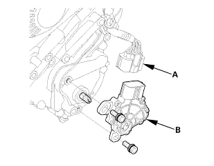
| 2. | Transmission Range Switch |
|
|
|
| 3. | Transmission Range Switch Subharness |
|
|
|
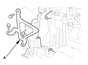
| 4. | ATF Warmer Bracket |
|
|
|
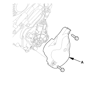
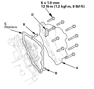
| 5. | Transmission End Cover |
|
|
|
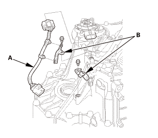
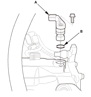
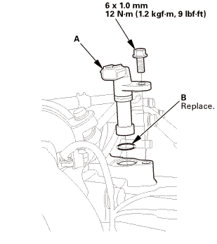
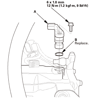
| 6. | Input Shaft (Mainshaft) Speed Sensor |
|
|
|
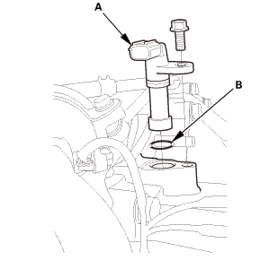
| 7. | Output Shaft (Countershaft) Speed Sensor |
|
|
|
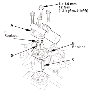
| 8. | A/T Clutch Pressure Control Solenoid Valve A |
|
|
|
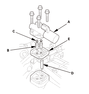
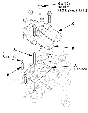
| 9. | A/T Clutch Pressure Control Solenoid Valve B and C |
|
|
|
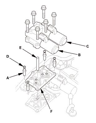
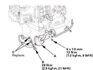
| 10. | ATF Filter Assembly |
|
|
|
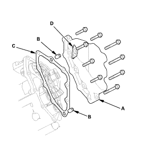
| 11. | A/T Solenoid Cover |
|
|
|
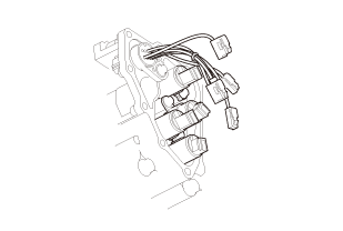
| 12. | A/T Shift Solenoid Wire Harness - Disconnection |
|
|
|
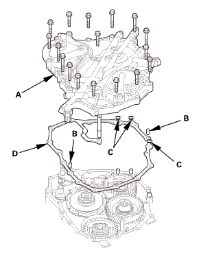
| 13. | ATF Pipe |
|
|
|
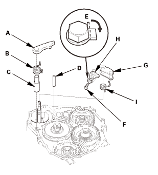
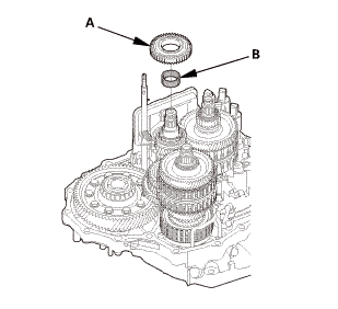
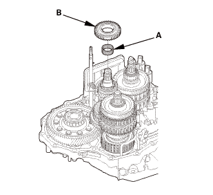
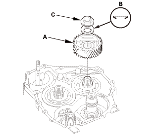
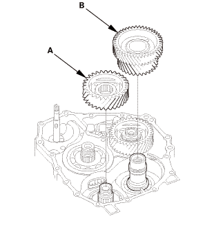
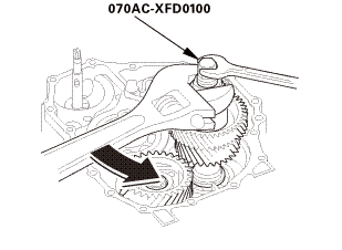
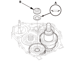
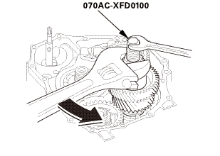
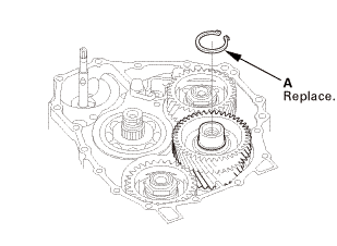
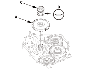
| 14. | End Cover Idler Gear Assembly |
|
|
|
|
|
|
||||||
|
|
|
||||||||||||||||||||||||
|
|
|
|
|
|
|
|
|
|
|
|
|
|
|
|
|
|
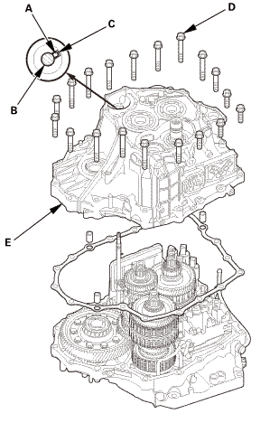
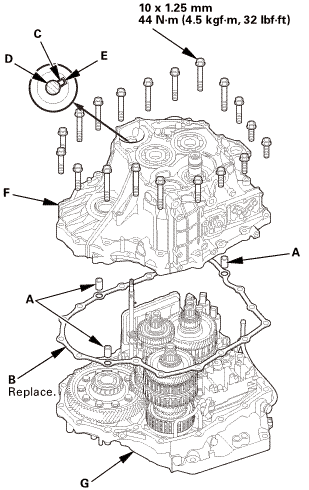
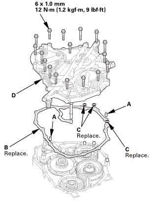
| 15. | A/T Transmission Housing |
|
|
|
||||||||||||||||||
| 16. | A/T Countershaft Reverse Gear |
|
|
|
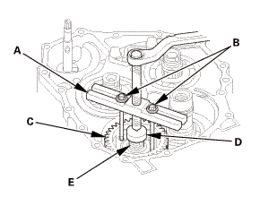
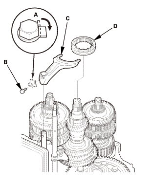
| 17. | Shift fork Shaft |
|
|
|
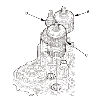
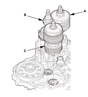
| 18. | A/T Mainshaft and Countershaft and Secondary Shaft Assembly |
|
|
|
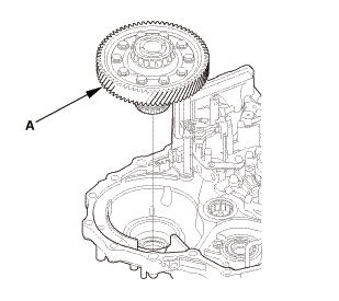
| 19. | A/T Differential Assembly |
|
|
|
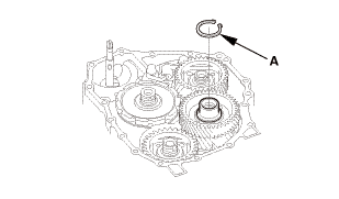
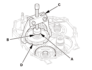
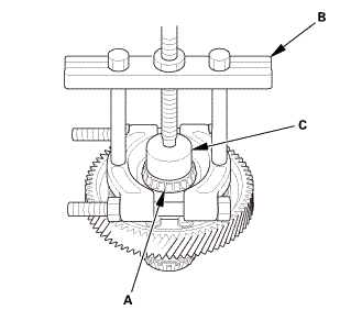
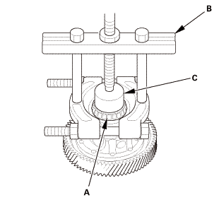
| 20. | Differential Carrier Bearing |
|
|
|

Installation
|
NOTE: |
|
|||
|
|||
|
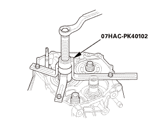
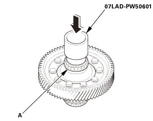
| 1. | Differential Carrier Bearing |
|
|
|
 a7laiz-pw5oau1
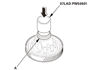
| 2. | A/T Differential Assembly |
|
|
|
| 3. | A/T Mainshaft and Countershaft and Secondary Shaft Assembly |
|
|
|
| 4. | Shift fork Shaft |
|
|
|
| 5. | A/T Countershaft Reverse Gear |
|
|
|
| 6. | A/T Transmission Housing |
|
|
|
||||||||||||||||||||||||
 1a1.2:mmmn!(4.:
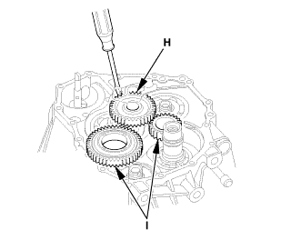
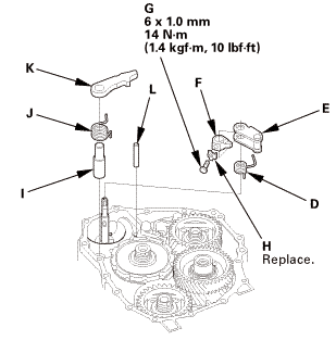
| 7. | End Cover Idler Gear Assembly |
|
|
|
|
|
|
|||||||||||||||||||||||||||||||||||
|
|
|
||||||||||||||||||||||||||||||
|
|
|
|||||||||
|
|
|
|||||||||||||||||||||
|
|
|
 o7aacxfnmoa
|
|
|
|
|
|
||||||||||||||||||||||||||||||||||||||||||||||||||||||
|
|
|
|||||||||||||||||||||||||||||||||||||||||||||||
|
|
|
|
|
|
|||||||||
|
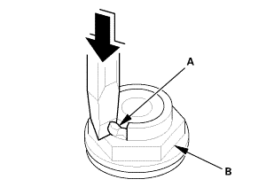
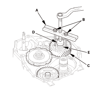
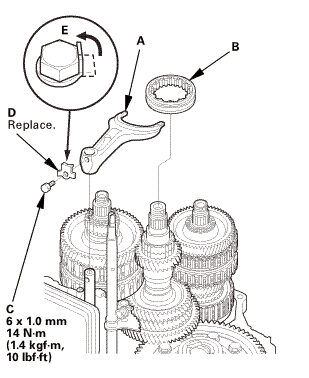
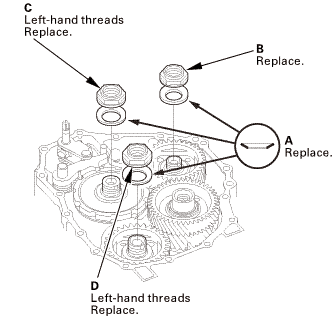
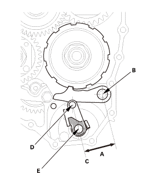
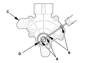
29. |
If the measurement is out of the standard, select and install the appropriate park lever stop (A) from the table. |
|
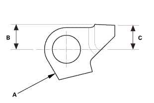
PARK LEVER STOP
|
|
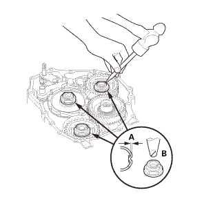
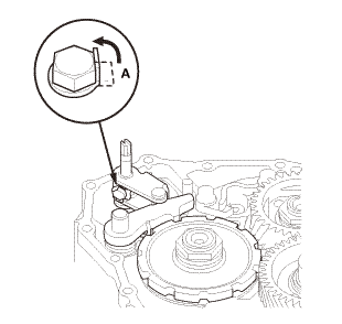
30. |
After replacing the park lever stop, make sure the distance is within the tolerance. |
|
|
|
| 8. | ATF Pipe |
|
|
|
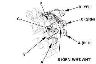
| 9. | A/T Shift Solenoid Wire Harness - Reconnection |
|
|
|
||||||||||||||||||||||
 lve.l(camwur,
| 10. | A/T Solenoid Cover |
|
|
|
 inmm
inmm| 11. | ATF Filter Assembly |
|
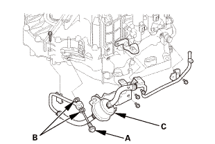
1. |
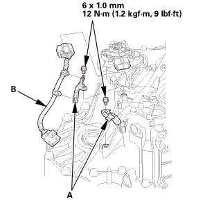
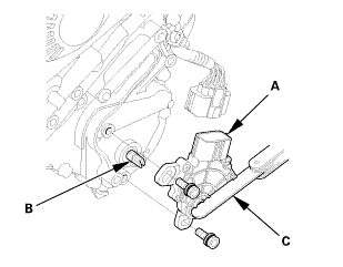
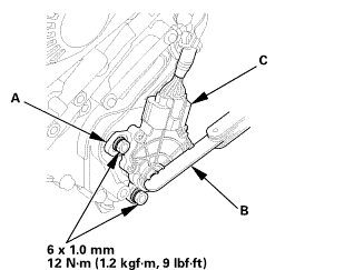
Install the ATF inlet line/ATF hose/ATF filter assembly (A). |
 himm12mm
|
2. |
Install the banjo bolt (B) using new sealing washers (C). |
| 12. | A/T Clutch Pressure Control Solenoid Valve B and C |
|
|
|
| 13. | A/T Clutch Pressure Control Solenoid Valve A |
|
|
|
 mmi11
mmi11| 14. | Output Shaft (Countershaft) Speed Sensor (A/T) |
|
|
|
| 15. | Input Shaft (Mainshaft) Speed Sensor |
|
|
|
| 16. | Transmission End Cover |
|
|
|
 mm12u....um,!mk)
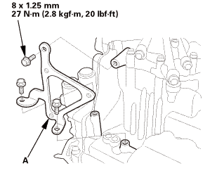
| 17. | ATF Warmer Bracket |
|
|
|
 mm27lhf!
| 18. | Transmission Range Switch Subharness |
|
|
|
| 19. | Transmission Range Switch |
|
|
|
||||||

|
|
|
||||||
|
|
|
|
|
|
||||||||||||
| 20. | Transmission Range Switch Cover |
|
|
|
 mmnm
mmnm Automatic
...
 A/T Gear Position Indicator Panel Assembly Removal and Installation (A/T, CVT)
NOTE: Do not wipe off the special grease applied to the area of the shift
lever marked with an asterisk (*) when you disassemble it.
1.
Shift Lever Knob and Shi ...
See also:
Honda Civic Owners Manual. Display Setup
You can change the brightness or color theme of the audio/information screen.
Changing the Screen Brightness
1. Select .
2. Select Settings.
3. Select System.
4. Select the Display tab.
5. Select Display Settings.
6. Select the setting you want.
7. Select OK.
Changing the Sc ...
