Honda Civic Service Manual: Torque Converter Housing Countershaft Bearing Replacement (A/T)
2301A8

Removal
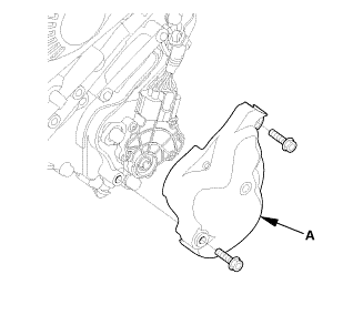
| 1. | Transmission Range Switch Cover |
|
|
|
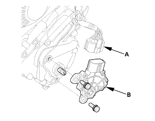
| 2. | Transmission Range Switch |
|
|
|
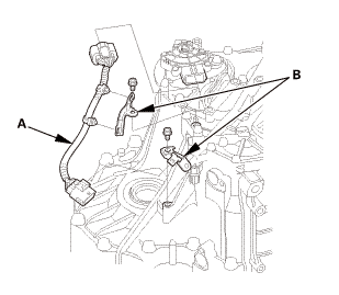
| 3. | Transmission Range Switch Subharness |
|
|
|
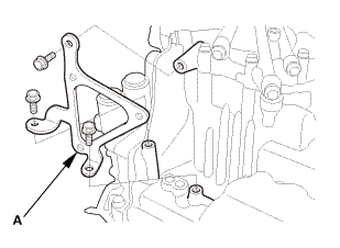
| 4. | ATF Warmer Bracket |
|
|
|
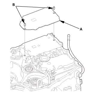
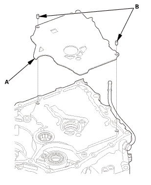
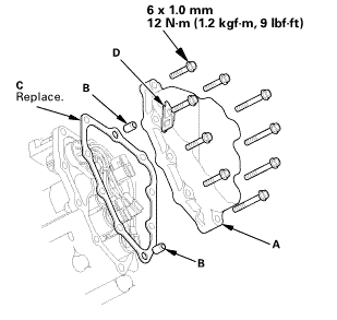
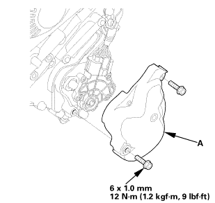
| 5. | Transmission End Cover |
|
|
|
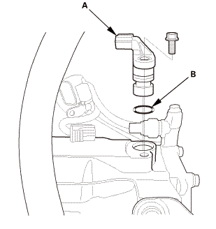
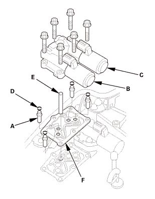
| 6. | Input Shaft (Mainshaft) Speed Sensor |
|
|
|
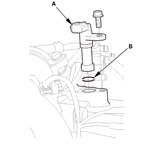
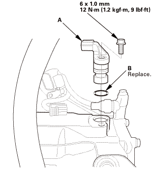
| 7. | Output Shaft (Countershaft) Speed Sensor |
|
|
|
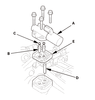
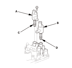
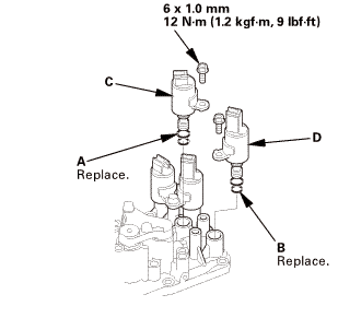
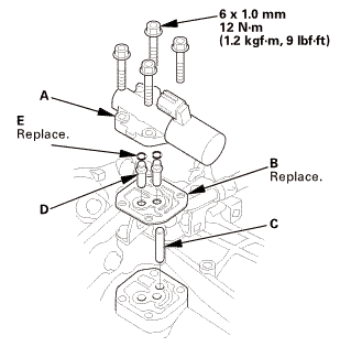
| 8. | A/T Clutch Pressure Control Solenoid Valve A |
|
|
|
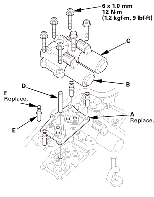
| 9. | A/T Clutch Pressure Control Solenoid Valve B and C |
|
|
|
| 10. | ATF Filter Assembly |
|
|
|
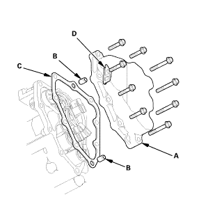
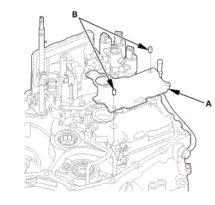
| 11. | A/T Solenoid Cover |
|
|
|
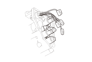
| 12. | A/T Shift Solenoid Wire Harness - Disconnection |
|
|
|
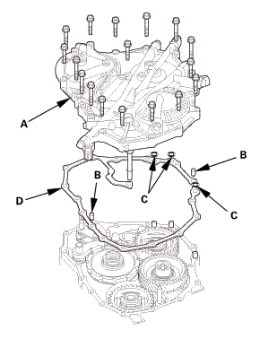
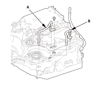
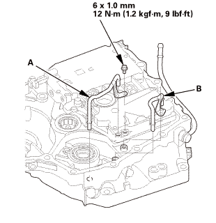
| 13. | ATF Pipe |
|
|
|
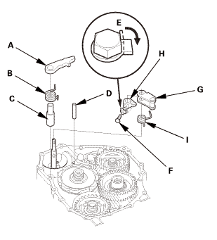
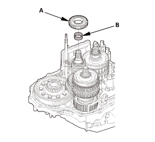
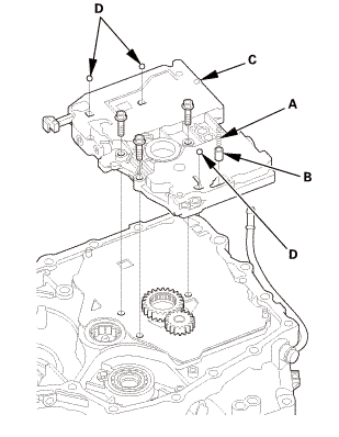
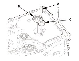
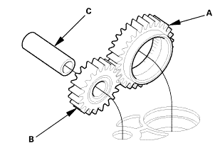
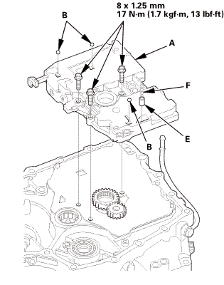
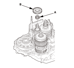
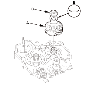
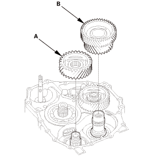
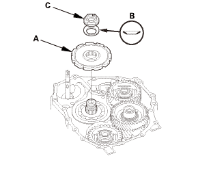
| 14. | End Cover Idler Gear Assembly |
|
|
|
|
|
|
||||||
|
|
|
||||||||||||||||||||||||

|
|
|
|
|
|
|
|
|
|
|
|
|
|
|
|
|
|
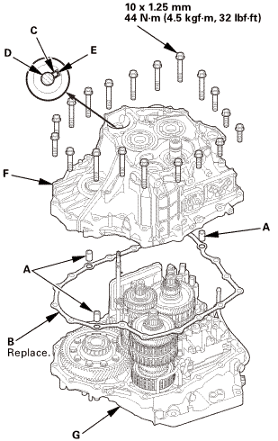
| 15. | A/T Transmission Housing |
|
|
|
||||||||||||||||||
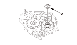
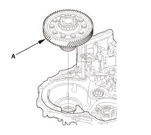
| 16. | A/T Countershaft Reverse Gear |
|
|
|
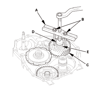
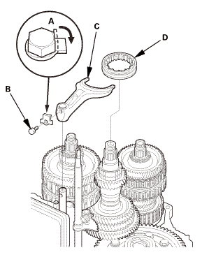
| 17. | Shift fork Shaft |
|
|
|
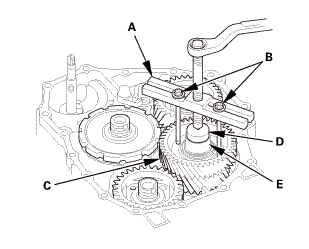
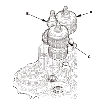
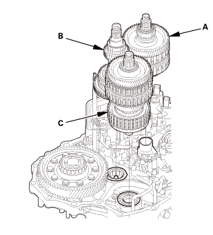
| 18. | A/T Mainshaft and Countershaft and Secondary Shaft Assembly |
|
|
|
| 19. | A/T Differential Assembly |
|
|
|
| 20. | A/T Regulator Valve Body |
|
|
|
|
|
|
|
|
|
| 21. | Shift Solenoid Valve |
|
|
|
|
|
|
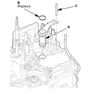
| 22. | Selector Control Shaft |
|
|
|
|
|
|
|
|
|
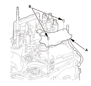
| 23. | ATF Strainer |
|
|
|
|
|
|
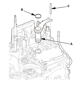
| 24. | A/T Servo Body |
|
|
|
|
|
|
|
|
|
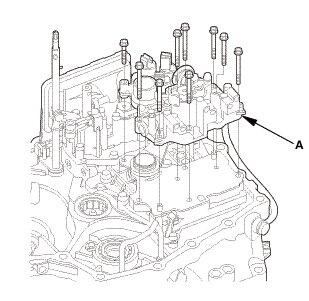
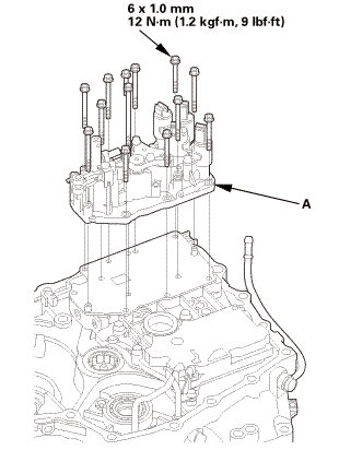
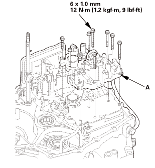
| 25. | A/T Main Valve Body |
|
|
|
|
|
|
|||||||||
|
|
|
|
|
|
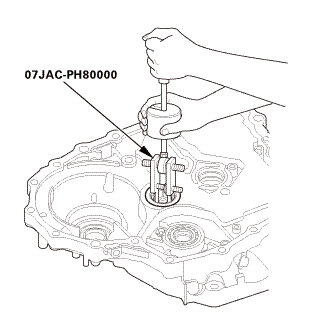
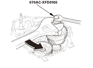
| 26. | A/T Countershaft Bearing |
|
|
|


Installation
|
NOTE: Apply a light coat of clean ATF on all moving parts before installation. |
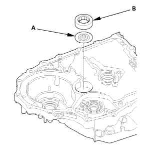
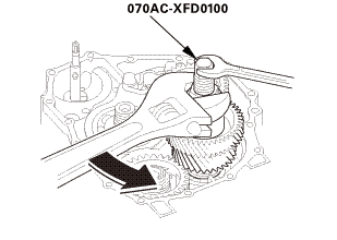
| 1. | A/T Countershaft Bearing |
|
|
|
|
|
|
|||||||||
| 2. | A/T Main Valve Body |
|
|
|
|
|
|
|||||||||

|
|
|
||||||||||||||||||
 ixusmm11
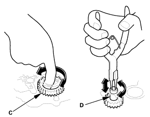
|
|
|
 12[12
12[12| 3. | A/T Servo Body |
|
|
|

|
|
|
|
|
|
 mm
mm| 4. | ATF Strainer |
|
|
|
| 5. | Selector Control Shaft |
|
|
|
|
|
|
|
|
|
| 6. | Shift Solenoid Valve |
|
|
|
||||||||||||||||||
|
|
|
| 7. | A/T Regulator Valve Body |
|
|
|
|
|
|
|
|
|
 i.mmmu
| 8. | A/T Differential Assembly |
|
|
|
| 9. | A/T Mainshaft and Countershaft and Secondary Shaft Assembly |
|
|
|
| 10. | Shift fork Shaft |
|
|
|
| 11. | A/T Countershaft Reverse Gear |
|
|
|
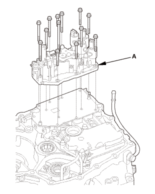
| 12. | A/T Transmission Housing |
|
|
|
||||||||||||||||||||||||
 1a1.2:mmmn!(4.:
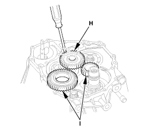
| 13. | End Cover Idler Gear Assembly |
|
|
|
|
|
|
|||||||||||||||||||||||||||||||||||
|
|
|
||||||||||||||||||||||||||||||
|
|
|
|||||||||
|
|
|
|||||||||||||||||||||
|
|
|
 o7aacxfnmoa
|
|
|
|
|
|
||||||||||||||||||||||||||||||||||||||||||||||||||||||
|
|
|
|||||||||||||||||||||||||||||||||||||||||||||||
|
|
|
|
|
|
|||||||||
|
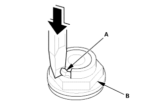
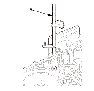
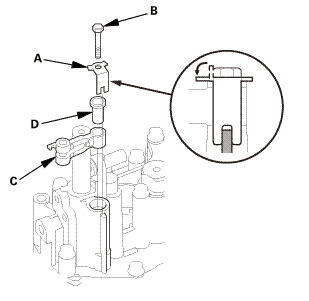
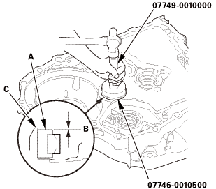
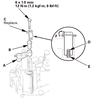
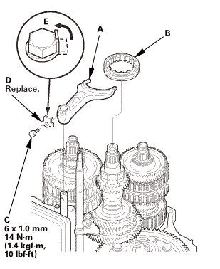
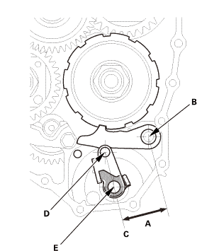
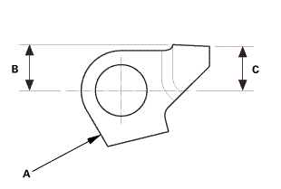
29. |
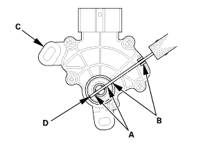
If the measurement is out of the standard, select and install the appropriate park lever stop (A) from the table. |
|
PARK LEVER STOP
|
|
30. |
After replacing the park lever stop, make sure the distance is within the tolerance. |
|
|
|
| 14. | ATF Pipe |
|
|
|
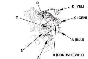
| 15. | A/T Shift Solenoid Wire Harness - Reconnection |
|
|
|
||||||||||||||||||||||
 lve.l(camwur,
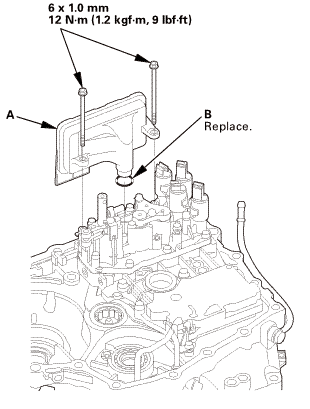
| 16. | A/T Solenoid Cover |
|
|
|
 inmm
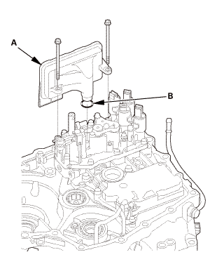
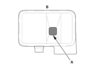
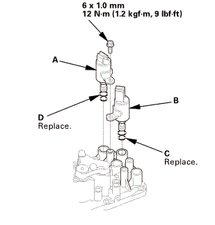
inmm| 17. | ATF Filter Assembly |
|
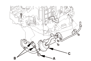
1. |
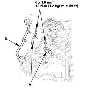
Install the ATF inlet line/ATF hose/ATF filter assembly (A). |
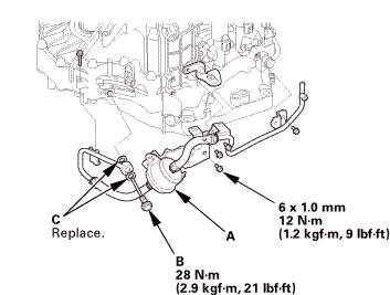 himm12mm
|
2. |
Install the banjo bolt (B) using new sealing washers (C). |
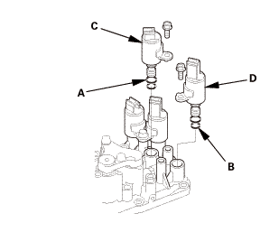
| 18. | A/T Clutch Pressure Control Solenoid Valve B and C |
|
|
|
| 19. | A/T Clutch Pressure Control Solenoid Valve A |
|
|
|
 mmi11
mmi11| 20. | Output Shaft (Countershaft) Speed Sensor (A/T) |
|
|
|
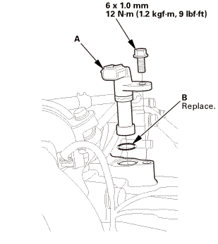
| 21. | Input Shaft (Mainshaft) Speed Sensor |
|
|
|
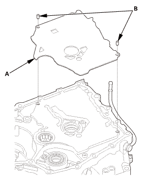
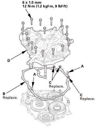
| 22. | Transmission End Cover |
|
|
|
 mm12u....um,!mk)
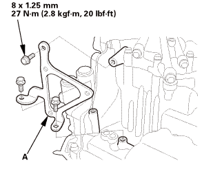
| 23. | ATF Warmer Bracket |
|
|
|
 mm27lhf!
| 24. | Transmission Range Switch Subharness |
|
|
|
| 25. | Transmission Range Switch |
|
|
|
||||||

|
|
|
||||||
|
|
|
|
|
|
||||||||||||
| 26. | Transmission Range Switch Cover |
|
|
|
 mmnm
mmnm Torque Converter
...
 Torque Converter Housing Secondary Shaft Bearing Replacement (A/T)
Removal
1.
Transmission Range Switch Cover
1.
Remove the transmission range switch cover (A).
...
See also:
Honda Civic Owners Manual. Front Seat Heaters
The ignition switch must be in ON (w*1 to use
the seat heaters
Press the seat heater button:
Once - The HI setting (three indicators on)
Twice - The MID setting (two indicators on)
Three times - The LO setting (one indicator on)
Four times - The OFF setting (no indicators on)
*1: Mode ...
