Honda Civic Service Manual: Moonroof Drain Tube Removal and Installation (4-door)

Removal
| 1. |
Battery Terminal (SRS) - Disconnection |
|
|
|
1.
|
Make sure the ignition switch is in LOCK (0).
|
|
2.
|
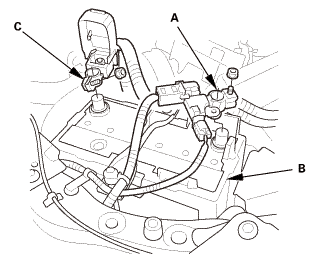
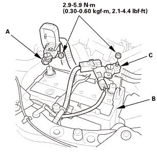
Disconnect and isolate the negative cable and battery
sensor (A) from the battery (B).
|
|
NOTE: Always disconnect the negative side first.
|
|
3.
|
Disconnect the positive cable (C) from the battery.
|
|
4.
|
Wait at least 3 minutes before starting work.
|
|
|
|
|
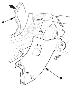
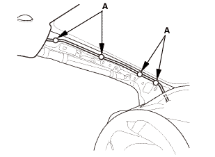
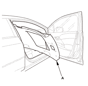
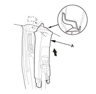
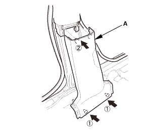
1.
|
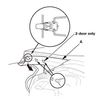
Pull out the A-pillar trim (A) to release the clips.
|
|
|
|
|
2.
|
Put a shop towel (A) in the opening between the A-pillar
trim (B) and the dashboard to prevent dropping the A-pillar
clips.
|
|
|
|
|
3.
|
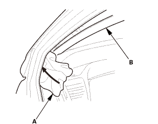
Disconnect the connector (A), then remove the A-pillar
trim (B).
|
|
NOTE: The upper clip (C) will stay in the body.
|
|
|
|
|
4.
|
Remove the upper clip (A) from the body.
|
|
5.
|
Repeat on the opposite side.
|
|
| 3. |
Front Door Opening Seal As Needed Both |
|

|
|
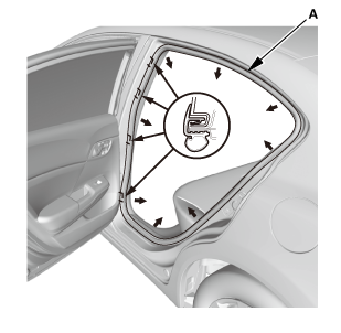
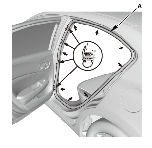
1.
|
Remove front door opening seal (A) as needed.
|
|
2.
|
Repeat on the opposite side.
|
|
|
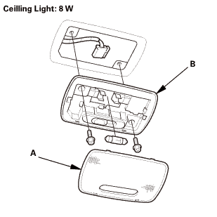 llghr llghr
|
|
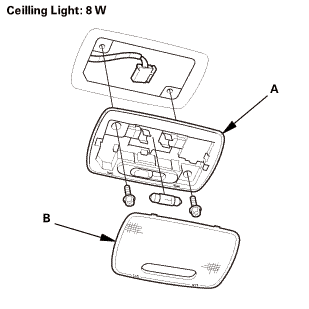
1.
|
Turn the ceiling light switch OFF.
|
|
2.
|
Carefully pry off the lens (A).
|
|
3.
|
Remove the ceiling light (B).
|
|
4.
|
Disconnect the connector.
|
|
| 5. |
Both Front Door Sill Trims |
|

|
|
1.
|
Driver's side: Remove the cap (A) from the front door
sill trim (B).
|
|
2.
|
Driver's side: Remove the opener lock cylinder (C).
|
|
|
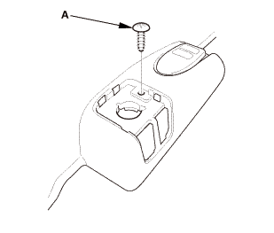
|
|
3.
|
Driver's side: Remove the screw (A).
|
|
|
Driver's side
Passenger's side

|
|
4.
|
Remove both front door sill trims (A).
|
|
| 6. |
Both Rear Door Sill Trims |
|
|
|
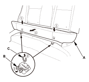
1.
|
While pushing down on the rear seat cushion (A), pull
the seat hook handle (B) to release the hook (C).
|
|
2.
|
While pulling up the seat cushion, remove the rear door
sill trim (D).
|
|
3.
|
The left side is shown; repeat on the right side.
|
|
| 7. |
Both Rear Door Opening Seals as Needed |
|
|
|
1.
|
Remove the rear door opening seal (A) as needed.
|
|
2.
|
The left side is shown; repeat on the right side.
|
|
| 8. |
Both B-Pillar Lower Trims |
|
|
|
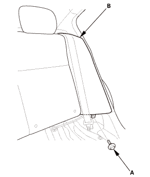
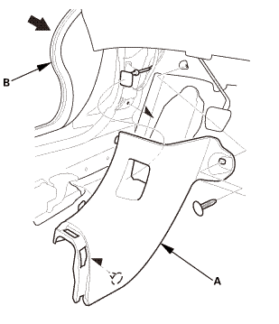
1.
|
Slide the front seat forward fully.
|
|
2.
|
Remove the B-pillar lower trim (A).
|
|
3.
|
The left side is shown; repeat on the right side.
|
|
| 9. |
Both Front Seat Belt Lower Anchor Bolts |
|
|
|
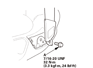
1.
|
Remove the anchor cover (A).
|
|
2.
|
The driver's seat is shown; repeat on the passenger's
seat.
|
|
|
|
|
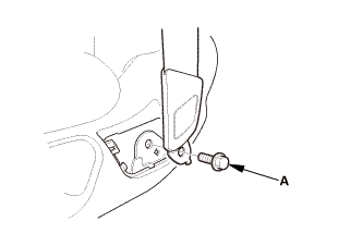
3.
|
Remove the lower anchor bolt (A).
|
|
4.
|
The driver's seat is shown; repeat on the passenger's
seat.
|
|
| 10. |
Both B-Pillar Upper Trims |
|
|
|
1.
|
Remove the bottom area of the B-pillar upper trim (A).
|
|
2.
|
The left side is shown; repeat on the right side.
|
|
|

|
|
3.
|
Remove the upper area of the B-pillar upper trim (A).
|
|
4.
|
The left side is shown; repeat on the right side.
|
|
|
|
|
5.
|
Pass the front seat belt lower anchor (A) out through
the hole in the slider (B), then remove the B-pillar upper
trim (C).
|
|
6.
|
The left side is shown; repeat on the right side.
|
|
|
|
|
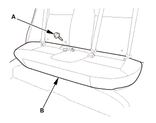
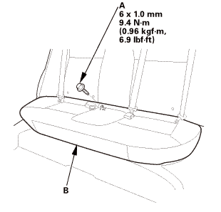
1.
|
Remove the bolt (A) securing the rear seat cushion (B).
|
|
|
|
|
2.
|
While pushing down the rear seat cushion (A), pull the
seat hook handles (B) to release the hooks (C).
|
|
3.
|
Remove the rear seat cushion.
|
|
| 12. |
Both Rear Seat Side Bolsters |
|
|
|
1.
|
Remove the bolt (A) securing the rear seat side bolster
(B).
|
|
2.
|
The left side is shown; repeat on the right side.
|
|
|
|
|
3.
|
Remove the rear seat side bolster (A).
|
|
4.
|
The left side is shown; repeat on the right side.
|
|
|
|
|
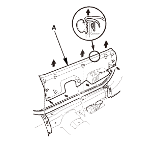
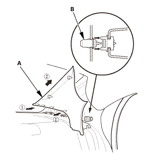
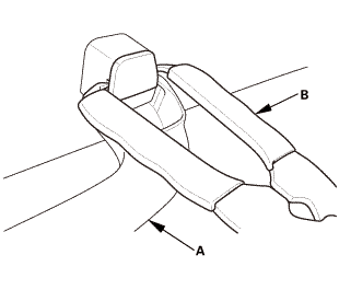
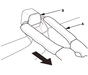
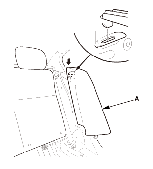
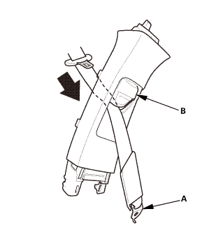
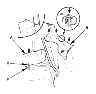
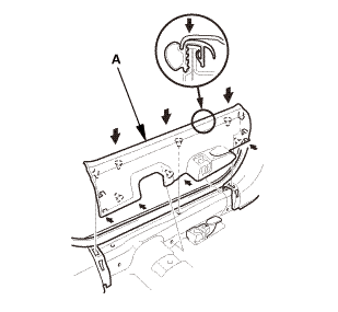
1.
|
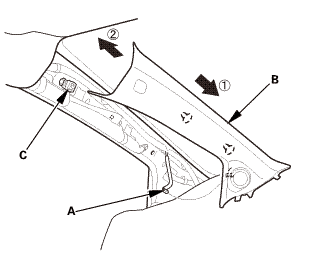
Pull out the C-pillar trim (A) to release the clips.
|
|
2.
|
Remove the C-pillar trim.
|
|
NOTE: The front clip (B) will stay in the body.
|
|
3.
|
The left side is shown; repeat on the right side.
|
|
|
|
|
4.
|
Remove the front clip (A).
|
|
5.
|
The left side is shown; repeat on the right side.
|
|
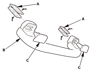
| 14. |
Grab Handles for One Vehicle |
|
|
|
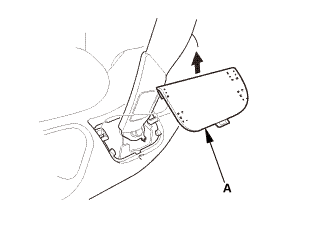
1.
|
Lower the grab handle (A).
|
|
2.
|
Insert the tips of the push pin/grab rail cap pliers
(B) into the notch.
|
|
|
|
|
3.
|
Gently squeeze the handles of the push pin/grab rail
cap pliers (A), and pull the cap (B) straight out.
|
|
|
|
|
4.
|
Remove the grab handle (A).
|
|
|
Driver's side
Passenger's side
|
|
1.
|
Pull out both front door opening seals (A) as needed.
|
|
2.
|
Remove both kick panels (B).
|
|
|
|
|
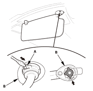
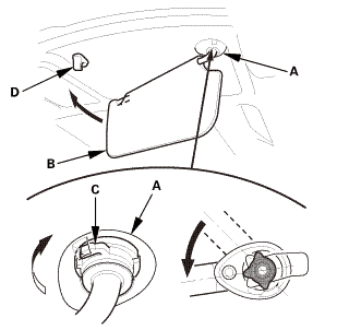
1.
|
Push the hook (A) with a flat-tip screwdriver through
the hole in the front side of the bracket cover (B).
|
|
NOTE: Make sure the hook is unlocked.
|
|
|
|
|
2.
|
While pushing in the hook (A) with a flat-tip screwdriver,
release the sunvisor (B) from the holder (C), and rotate
the sunvisor backward 45 °.
|
|
NOTE: Make sure the hook slides into the bracket cover
as you rotate the sunvisor.
|
|
|
|
|
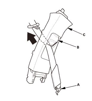
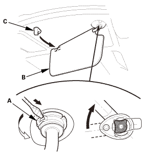
3.
|
Disconnect the connector (A), then remove the sunvisor
(B).
|
|
NOTE: If the sunvisor cannot be removed, the hook has
not rotated into the bracket cover. Repeat step 2 to rotate
the hook.
|
|
|
|
|
4.
|
If necessary, turn the sunvisor holder (A) 45 ° counterclockwise,
then remove it from the holder grommet (B).
|
|
|
|
|
5.
|
If necessary, remove the holder grommet (A).
|
|
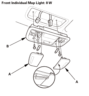
| 17. |
Front Individual Map Light (without moonroof) |
|
|
|
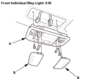
1.
|
Turn the front individual map light switch OFF.
|
|
2.
|
Carefully pry off the lenses (A) with a flat-tip screwdriver.
|
|
3.
|
Disconnect the connector.
|
|
4.
|
Remove the front individual map light (B).
|
|
|
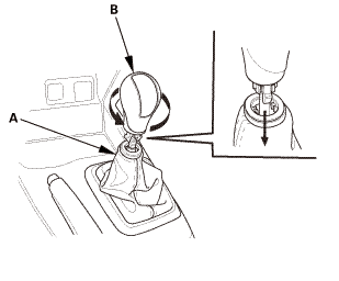
Except K24Z7 engine
|
|
1.
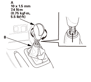
|
Except K24Z7 engine: Lower the shift lever boot (A) to
release the hooks from the boot.
|
|
2.
|
Except K24Z7 engine: Remove the shift lever knob (B).
|
|
|
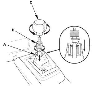
K24Z7 engine
|
|
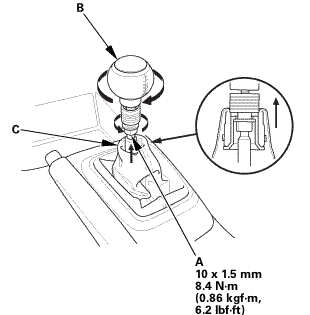
3.
|
K24Z7 engine: Lower the shift lever boot (A) to release
the hooks from the boot.
|
|
4.
|
K24Z7 engine: Loosen the shift lever boot ring (B).
|
|
5.
|
K24Z7 engine: Remove the shift lever knob (C).
|
|
6.
|
K24Z7 engine: Remove the shift lever boot ring.
|
|
| 19. |
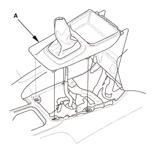
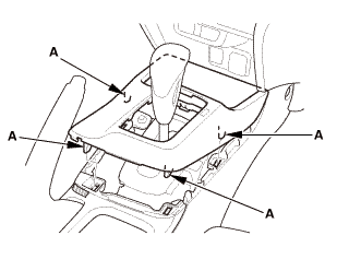
Center Console Panel Assembly (M/T) |
|
|
|
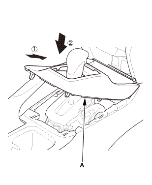
1.
|
Remove the center console panel (A).
|
|
| 20. |
Center Console Panel Assembly (A/T) |
|

|
|
2.
|
Remove the center console panel (A).
|
|
| 21. |
Cup Holder Panel Assembly |
|
|
|
1.
|
Remove the cup holder panel assembly (A).
|
|
|
|
|
2.
|
Disconnect the connector (B).
|
|
|
|
|
3.
|
Remove the console box mat (A).
|
|
|
|
|
5.
|
Disconnect the connector (A).
|
|
|
|
|
6.
|
Remove the center console (A).
|
|
| 23. |
Center Console Bracket (M/T) |
|
|
|
1.
|
M/T: Remove the center console bracket (A).
|
|
|
|
|
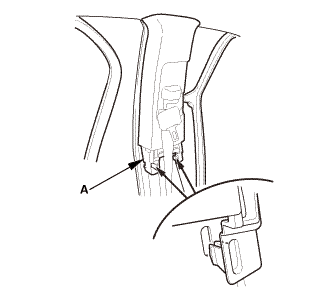
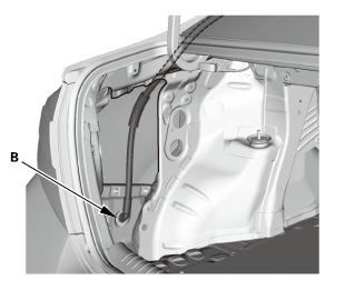
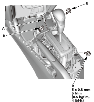
1.
|
Without moonroof: From the driver's A-pillar, detach
the harness clips (A).
|
|
|
|
|
2.
|
Without moonroof: From under the driver's dash, disconnect
the connector (A), and detach the harness clips (B).
|
|
|

|
|
3.
|
From the passenger's A-pillar, disconnect the connector
(A), and detach the harness clips (B).
|
|
|
|
|
4.
|
For some models: Release the glove box stops (A) on each
side of the dashboard.
|
|
|
|
|
5.
|
For some models: From the glove box opening, disconnect
the connector (A), and detach the harness clip (B).
|
|
|
|
|
6.
|
From the right C-pillar, disconnect the connector (A),
and detach the harness clip (B).
|
|
|
|
|
7.
|
From the left C-pillar, disconnect the terminal (A),
and remove the bolt (B), then detach the harness clip (C).
|
|
|
M/T
A/T
|
|
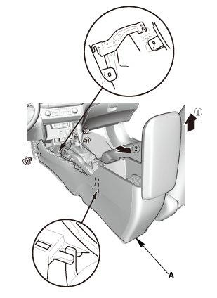
8.
|
Remove the bolts (A) securing the shift lever assembly
(B).
|
|
9.
|
Lay the shift lever assembly down as needed.
|
|
|
Without moonroof
With moonroof
|
|
10.
|
Slide the front seat all the way back, and recline the
seat-back fully.
|
|
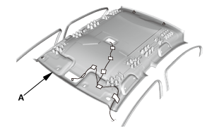
11.
|
With the help of an assistant, lower the headliner (A).
|
|
|
|
|
12.
|
With the help of an assistant, remove the headliner (A)
through the passenger's front door opening.
|
|
NOTE: Do not bend the headliner. Bending the headliner
will crease and damage it.
|
|
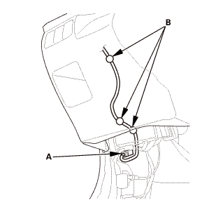
| 25. |
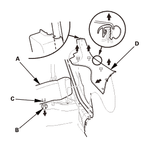
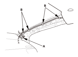
Moonroof Front Drain Tube Both |
|
|
|
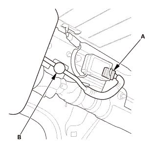
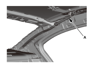
1.
|
Disconnect the moonroof front drain tube (A).
|
|
2.
|
Pull out the moonroof front drain valve (B).
|
|
3.
|
Tie a string to the top end of the moonroof front drain
tube, then pull down the drain tube out of the A-pillar.
|
|
4.
|
Leave the string in the pillar to use when reinstalling
the moonroof front drain tube.
|
|
5.
|
Repeat on the opposite side.
|
|
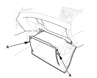
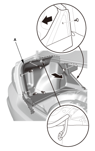
|
|
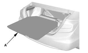
|
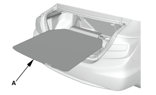
1.
|
Remove the trunk floor cover (A).
|
|
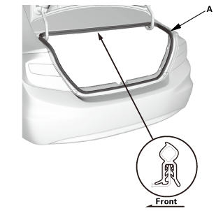
| 27. |
Trunk Lid Weatherstrip As Needed |
|
|
|
1.
|
Remove the trunk lid weatherstrip (A) as needed.
|
|
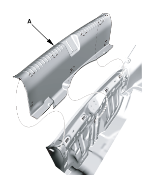
| 28. |
Trunk Rear Trim Panel |
|
|
|
1.
|
Remove the trunk rear trim panel (A).
|
|
| 29. |
Trunk Side Trim Panel Both |
|
|
|
1.
|
Remove the trunk side trim panel (A).
|
|
2.
|
Repeat on the opposite side.
|
|
| 30. |
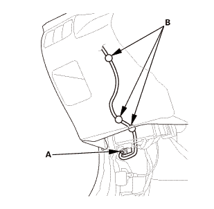
Moonroof Rear Drain Tube Both |
|
|
|
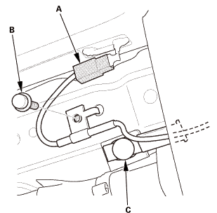
1.
|
Disconnect the moonroof rear drain tube (A).
|
|
2.
|
Pull out the moonroof rear drain valve (B).
|
|
3.
|
Tie a string to the top end of the moonroof rear drain
tube, then pull down the drain tube out of the pillar.
|
|
4.
|
Leave the string in the pillar to use when reinstalling
the moonroof rear drain tube.
|
|
5.
|
Repeat on the opposite side.
|
|

Installation
| 1. |
Moonroof Rear Drain Tube Both |
|
|
|
1.
|
Tie the string that was left in the pillar to the top
end of the new moonroof rear drain tube (A) and pull it
up into the roof.
|
|
2.
|
Connect the moonroof rear drain tube.
|
|
3.
|
Install the moonroof rear drain valve (B).
|
|
4.
|
Repeat on the opposite side.
|
|
| 2. |
Trunk Side Trim Panel Both |
|

|
|
1.
|
Install the trunk side trim panel (A).
|
|
2.
|
Repeat on the opposite side.
|
|
|

|
|
1.
|
Install the trunk rear trim panel (A).
|
|
| 4. |
Trunk Lid Weatherstrip as Needed |
|
|
|
1.
|
Install the trunk lid weatherstrip (A).
|
|
|
|
|
1.
|
Install the trunk floor cover (A).
|
|
| 6. |
Moonroof Front Drain Tube Both |
|
|
|
1.
|
Tie the string that was left in the A-pillar to the top
end of the new moonroof front drain tube (A) and pull it
up into the roof.
|
|
2.
|
Connect the moonroof front drain tube.
|
|
3.
|
Install the moonroof front drain valve (B).
|
|
4.
|
Repeat on the opposite side.
|
|
|
|
|
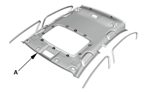
1.
|
With the help of an assistant, take the headliner (A)
in through the passenger's front door opening.
|
|
NOTE: Do not bend the headliner. Bending the headliner
will crease and damage it.
|
|
|
Without moonroof
With moonroof
|
|
2.
|
With the help of an assistant, install the headliner
(A).
|
|
|
M/T
A/T
|
|
3.
|
Install the bolts (A) securing the shift lever assembly
(B).
|
|
|
|
|
4.
|
At the left C-pillar, connect the terminal (A), and install
the bolt (B), then install the harness clip (C).
|
|
|
|
|
5.
|
At the right C-pillar, connect the connector (A), and
install the harness clip (B).
|
|
|
|
|
6.
|
For some models: At the glove box opening, connect the
connector (A), and install the harness clip (B).
|
|
|

|
|
7.
|
For some models: Install the glove box stops (A) on each
side of the dashboard.
|
|
|
|
|
8.
|
At the passenger's A-pillar, connect the connector (A),
and install the harness clips (B).
|
|
|
|
|
9.
|
Without moonroof: Under the driver's dash, connect the
connector (A), and install the harness clips (B).
|
|
|

|
|
10.
|
Without moonroof: At the driver's A-pillar, install the
harness clips (A).
|
|
| 8. |
Center Console Bracket (M/T) |
|
|
|
1.
|
M/T: Install the center console bracket (A).
|
|
|

|
|
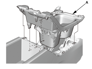
1.
|
Install the center console (A).
|
|
|
|
|
2.
|
Connect the connector (A).
|
|
|
|
|
3.
|
Install the bolts (A).
|
|
4.
|
Install the console box mat (B).
|
|
|
|
|
5.
|
Connect the connector (A).
|
|
6.
|
Install the bolts (B).
|
|
| 10. |
Cup Holder Panel Assembly |
|
|
|
1.
|
Install the cup holder panel assembly (A).
|
|
| 11. |
Center Console Panel Assembly (A/T) |
|
|
|
1.
|
Install the center console panel (A).
|
|
|

|
|
2.
|
Install the clips (A).
|
|
| 12. |
Center Console Panel Assembly (M/T) |
|
|
|
1.
|
Install the center console panel (A).
|
|
|
Except K24Z7 engine
|
|
1.
|
Except K24Z7 engine: Install the shift lever knob (A).
|
|
NOTE: Tighten the shift lever knob until the shift pattern
is properly aligned.
|
|
2.
|
Except K24Z7 engine: Connect the shift lever boot (B).
|
|
|
K24Z7 engine
|
|
3.
|
K24Z7 engine: Install and turn the shift lever boot ring
(A) until it reaches the bottom of the threads on the shift
lever.
|
|
4.
|
K24Z7 engine: Turn the shift lever knob (B) until the
shift lever knob contacts the shift lever boot ring.
|
|
5.
|
K24Z7 engine: Tighten the shift lever boot ring and the
shift lever knob together with the shift pattern properly
aligned.
|
|
6.
|
K24Z7 engine: Connect the shift lever boot (C).
|
|
| 14. |
Front Individual Map Light (without moonroof) |
|
|
|
1.
|
Connect the connector.
|
|
2.
|
Install the front individual map light (A).
|
|
3.
|
Carefully install the lenses (B).
|
|
|
|
|
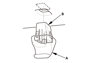
1.
|
Install the holder (A) into the holder grommet (B) by
turning it 45 ° clockwise.
|
|
2.
|
Install the holder and holder grommet as an assembly
into the body by pushing it until the hooks snap into place
securely.
|
|
|
|
|
3.
|
Connect the connector (A), and install the sunvisor (B).
|
|
|
|
|
4.
|
While holding the bracket cover (A), rotate the sunvisor
(B) forward until the hook (C) snaps into place.
|
|
5.
|
Gently pull down on the sunvisor to make sure it is properly
secured in the body.
|
|
6.
|
Rotate the sunvisor into the holder (D).
|
|
|
Driver's side
Passenger's side
|
|
1.
|
Install both kick panels (A).
|
|
2.
|
Install both front door opening seals (B) as needed.
|
|
| 17. |
Grab Handles for One Vehicle |
|
|
|
1.
|
Install the clips (A) on the grab handle (B).
|
|
2.
|
Install the caps (C) fully into the clips.
|
|
|
|
|
3.
|
Position the grab handle (A) on the grab handle bracket
(B).
|
|
4.
|
Push on the grab handle until the clips (C) snap into
place securely.
|
|
|

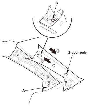
|
|
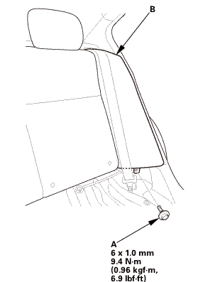
1.
|
Install the new front clip (A) to the C-pillar trim (B).
|
|
|
|
|
2.
|
Install the C-pillar trim (A).
|
|
NOTE:
|
|

|
Make sure the side curtain airbag is
not tucked under the clips or the ribs.
|
|
|
|
Do not push too hard on the C-pillar
trim. If you push too hard, the clip will
be damaged, and it will not hold the trim
properly.
|
|
|
|
Gently tug on the C-pillar trim to verify
that all clips are securely fastened.
|
|
|
|
3.
|
The left side is shown; repeat on the right side.
|
|
| 19. |
Both Rear Seat Side Bolsters |
|
|
|
1.
|
Install the rear seat side bolster (A).
|
|
2.
|
The left side is shown; repeat on the right side.
|
|
|
 mmmmlnss mmmmlnss
|
|
3.
|
Install the bolt (A) securing the rear seat side bolster
(B).
|
|
4.
|
The left side is shown; repeat on the right side.
|
|
|
|
|
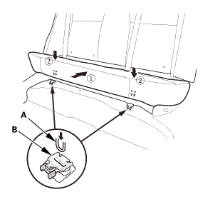
1.
|
Install the hooks (A) to the rear seat cushion clips
(B).
|
|
|
|
|
2.
|
Install the bolt (A) securing the rear seat cushion (B).
|
|
| 21. |
Both B-Pillar Upper Trims |
|
|
|
1.
|
Pass the front seat belt lower anchor (A) in through
the hole in the slider (B).
|
|
2.
|
The left side is shown; repeat on the right side.
|
|
|
|
|
3.
|
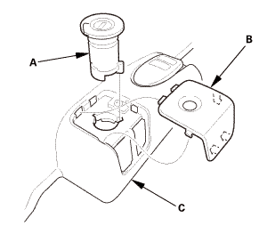
Install the upper area of the B-pillar upper trim (A).
|
|
4.
|
The left side is shown; repeat on the right side.
|
|
|
|
|
5.
|
Install the bottom area of the B-pillar upper trim (A).
|
|
6.
|
The left side is shown; repeat on the right side.
|
|
| 22. |
Both Front Seat Belt Lower Anchor Bolts |
|
 inmm inmm
|
|
1.
|
Install the lower anchor bolt (A).
|
|
2.
|
The driver's seat is shown; repeat on the passenger's
seat.
|
|
|
|
|
3.
|
Install the anchor cover (A).
|
|
4.
|
The driver's seat is shown; repeat on the passenger's
seat.
|
|
| 23. |
Both B-Pillar Lower Trims |
|
|
|
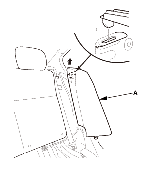
1.
|
Install the B-pillar lower trim (A).
|
|
2.
|
The left side is shown; repeat on the right side.
|
|
| 24. |
Both Rear Door Opening Seals as Needed |
|
|
|
1.
|
Install the rear door opening seal (A).
|
|
2.
|
The left side is shown; repeat on the right side.
|
|
| 25. |
Both Rear Door Sill Trims |
|
|
|
1.
|
While pulling up the rear seat cushion (A), install the
rear door sill trim (B).
|
|
2.
|
Push down the seat cushion, then install the hook (C)
to the rear seat cushion clip (D).
|
|
3.
|
The left side is shown; repeat on the right side.
|
|
| 26. |
Both Front Door Sill Trims |
|
Driver's side
Passenger's side
|
|
1.
|
Install both front door sill trims (A).
|
|
|
|
|
2.
|
Driver's side: Install the screw (A).
|
|
|
|
|
3.
|
Driver's side: Install the opener lock cylinder (A).
|
|
4.
|
Driver's side: Install the cap (B) to the front door
sill trim (C).
|
|
|
 cullingllghr cullingllghr
|
|
1.
|
Connect the connector.
|
|
2.
|
Install the ceiling light (A).
|
|
3.
|
Carefully install the lens (B).
|
|
| 28. |
Front Door Opening Seal as Needed Both |
|
|
|
1.
|
Install front door opening seal (A).
|
|
2.
|
Repeat on the opposite side.
|
|
|
|
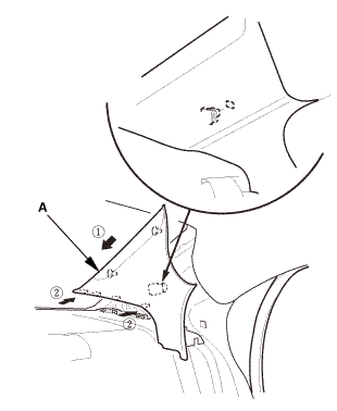
|
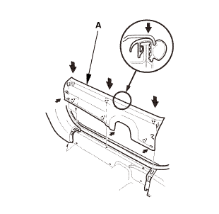
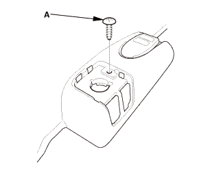
1.
|
Carefully install the new upper clip (A) to the A-pillar
trim (B).
|
|
|
|
|
2.
|
Connect the connector (A).
|
|
3.
|
Fit the clips into the holes in the A-pillar.
|
|
4.
|
Lightly push the A-pillar trim (B) into place, then install
the trim.
|
|
NOTE:
|
|
|
Make sure the side curtain airbag is
not tucked under the clips or the trim ribs.
|
|
|
|
Do not push too hard on the A-pillar
trim. If you push too hard, the clip will
be damaged, and it will not hold the trim
properly.
|
|
|
|
Gently tug on the A-pillar trim to verify
that all clips are securely fastened.
|
|
|
|
5.
|
Repeat on the opposite side.
|
|
| 30. |
Battery Terminal (SRS) - Reconnection |
|
 (o.2ao.sam. (o.2ao.sam.
|
|
NOTE: If the battery performs abnormally, test the battery.
|
|
1.
|
Clean the battery terminals.
|
|
2.
|
Connect the positive cable (A) to the battery (B).
|
|
NOTE: Always connect the positive side first.
|
|
3.
|
Connect the negative cable and battery sensor (C) to
the battery.
|
|
4.
|
Apply multipurpose grease to the terminals to prevent
corrosion.
|
|
8141D0
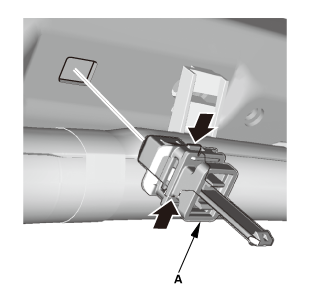
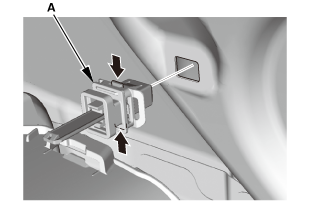
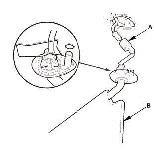
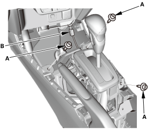
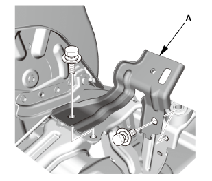
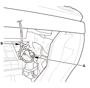
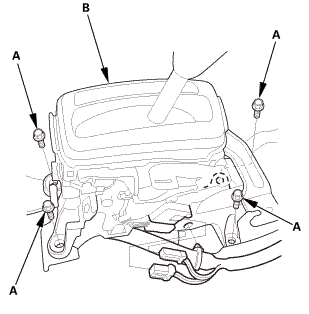
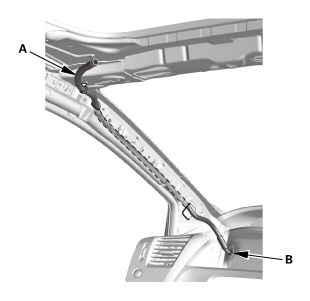
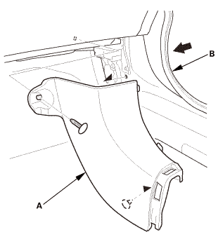
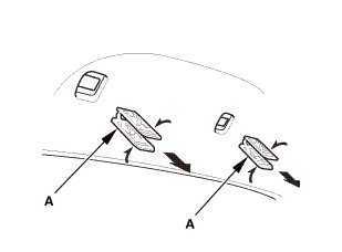
Removal
1.
Moonroof Link Cover Both
1.
Remove th ...
Removal
1.
Battery Terminal (SRS) - Disconnection
1.
Make s ...
See also:
Honda Civic Owners Manual. HFL Menus
The ignition switch must be in ACCESSORY
or ON
to use HFL.
HFL Menus
To use HFL, you must first pair your Bluetoothcompatible
cell phone to the system while the vehicle
is parked.
Some functions are limited while driving. A message
appears on the screen when the vehi ...
 Moonroof Drain Channel Removal and Installation (4-door)
 Moonroof Frame/Drain Channel Slider and Cable Assembly Removal and Installation
(2-door)
Moonroof Frame/Drain Channel Slider and Cable Assembly Removal and Installation
(2-door)