Honda Civic Service Manual: Manual Transmission Removal and Installation (R18Z1 M/T)
213101

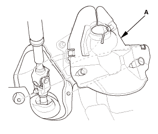
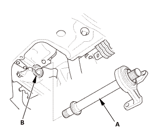
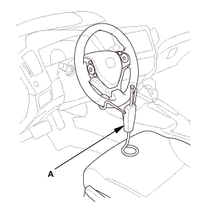
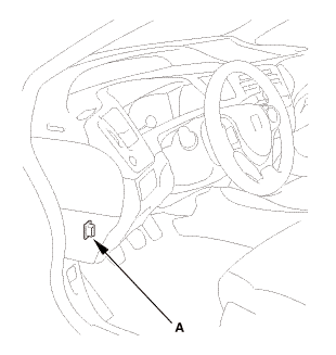
| 1. | Steering Joint Cover |
|
|
|
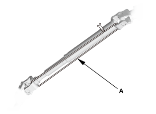
| 2. | Steering Column Lower Slide Shaft - Hold |
|
|
|
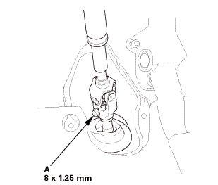
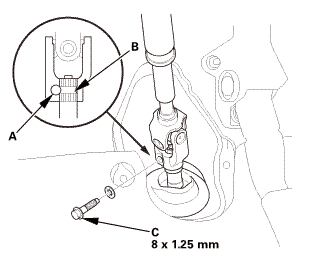
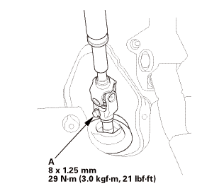
| 3. | Steering Joint Bolt - Loosen |
|
|
|
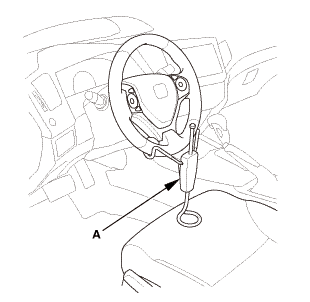
| 4. | Steering Wheel Hold |
|
|
|
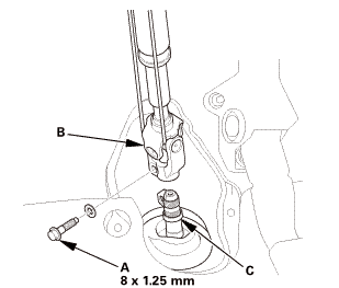
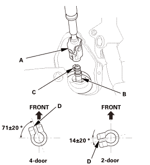
| 5. | Steering Joint - Disconnection |
|
|
|
||||||||||||||||||||

| 6. | Wide - Hood Open Position |
|
|
|
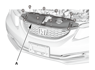
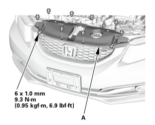
| 7. | Front Grille Cover |
|
|
|
|
|
|
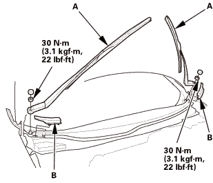
| 8. | Wiper Arm Assembly |
|
|
|
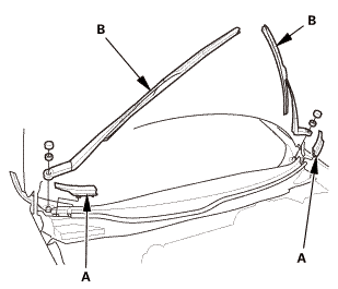
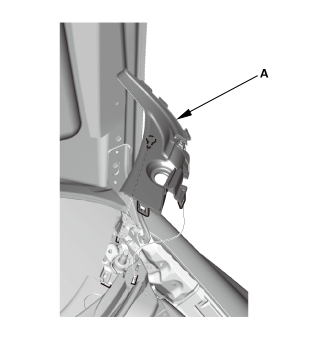
| 9. | Both Side Cowl Covers |
|
|
|
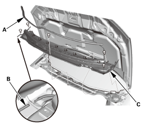
| 10. | Center Cowl Cover |
|
|
|

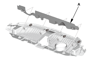
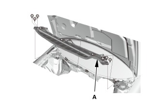
| 11. | Under Cowl Panel |
|
|
|
| 12. | Battery Terminal - Disconnection |
|
|
|
|||||||||||||||||||||||||||
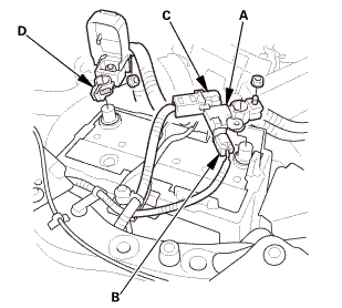
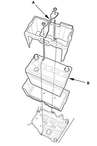
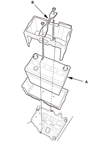
| 13. | Battery |
|
|
|
| 14. | Intake Air Pipe |
|
|
|
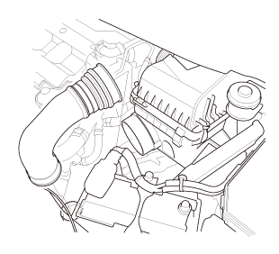
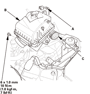
| 15. | Air Cleaner |
|
|
|
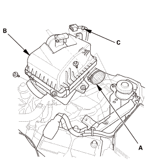
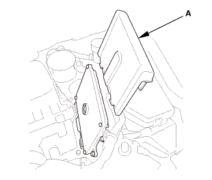
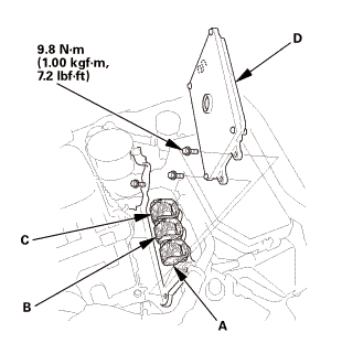
| 16. | ECM/PCM |
|
|
|
|
|
|
|||||||||
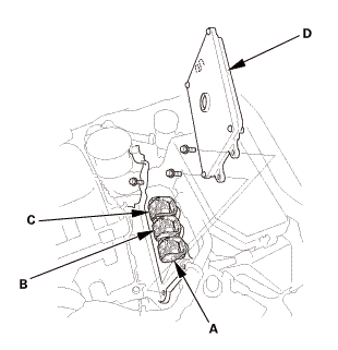
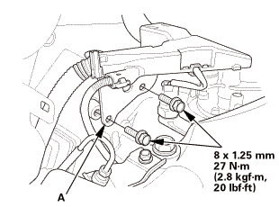
| 17. | Air Cleaner Bracket |
|
|
|
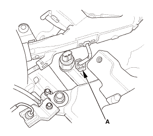
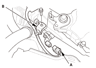
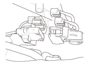
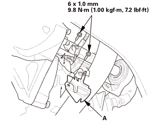
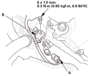
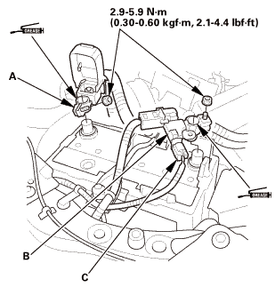
| 18. | Back-Up Light Switch Connector |
|
|
|
|
|
|
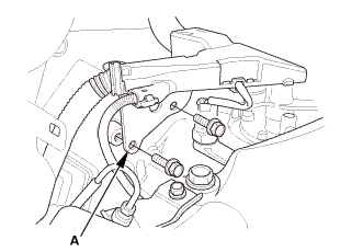
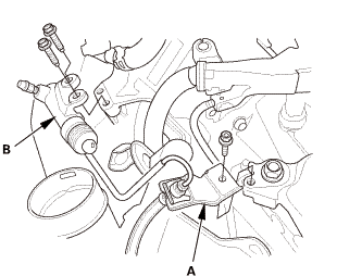
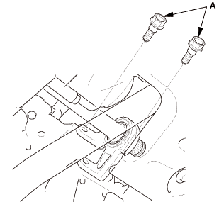
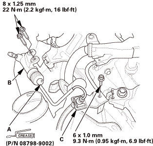
| 19. | Slave Cylinder |
|
|
|
|||||||||||||||||||||||
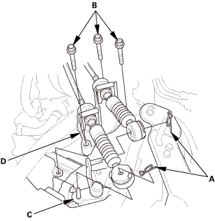
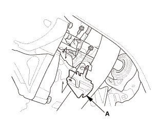
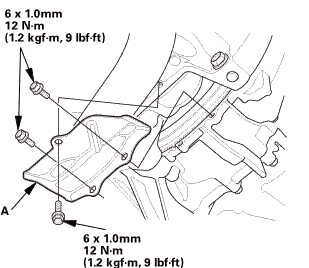
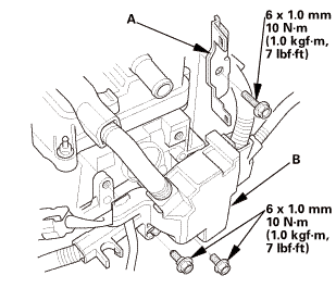
| 20. | Shift Cable Bracket |
|
|
|
| 21. | Transmission Peripheral Assembly Upper Side |
|
|
|
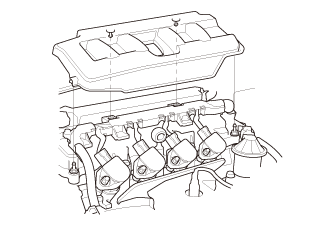
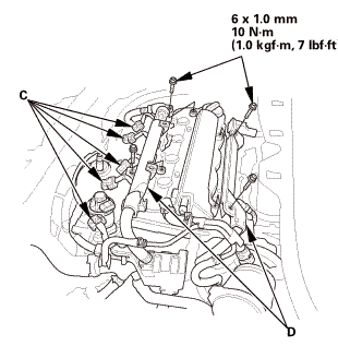
| 22. | Engine Cover |
|
|
|
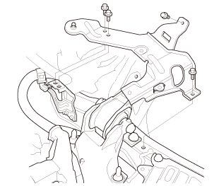
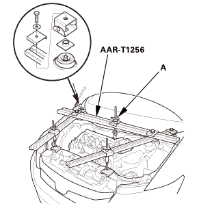
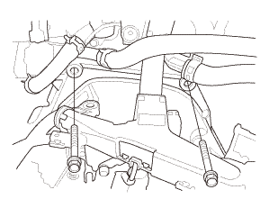
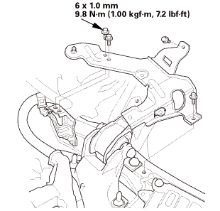
| 23. | Engine Support Hanger Peripheral Assembly |
|
|
|
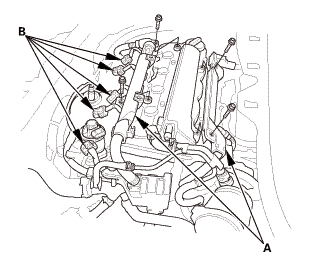
| 24. | Engine Support Hanger |
|
|
|
|
|
|
||||||||||||
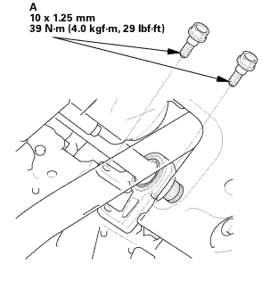
| 25. | Upper Transmission Mounting Bolt |
|
|
|
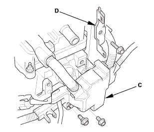
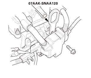
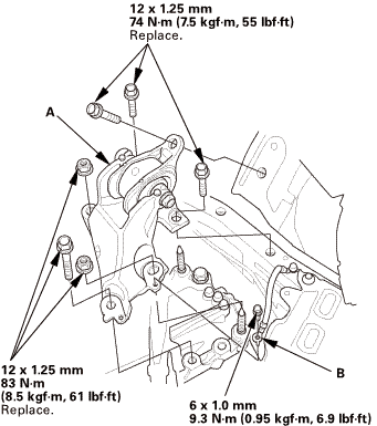
| 26. | Transmission Mount Assembly |
|
|
|
| 27. | Vehicle Lift |
|
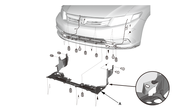
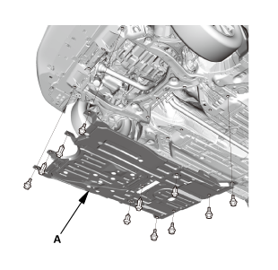
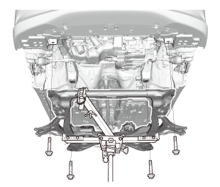
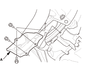
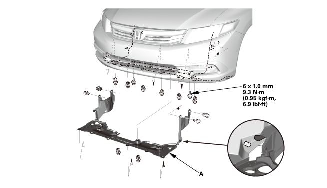
| 28. | Splash Shield |
|
1. |
Remove the splash shield (A). |
| 29. | Engine Undercover |
|
|
|
| 30. | MTF Replacement |
|
|
|
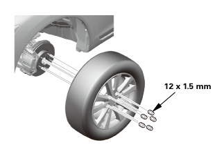
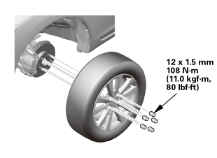
| 31. | Front Wheel |
|
|
|
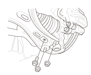
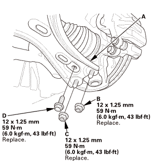
| 32. | Lower Arm Joint - Disconnection, Both Knuckle Side |
|
|
|
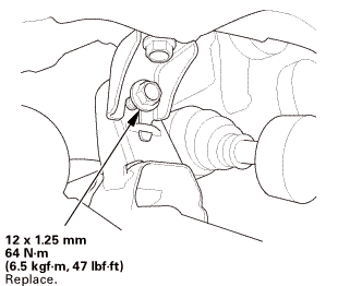
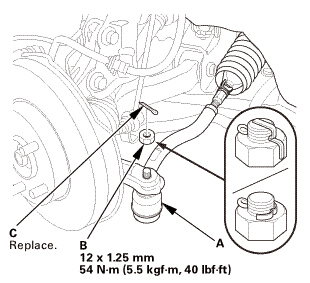
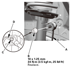
| 33. | Front Stabilizer Ball Joint, Both Damper Side - Disconnection |
|
|
|
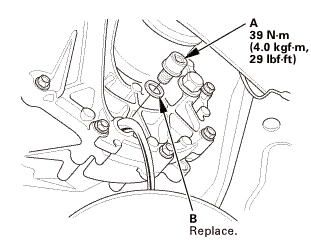
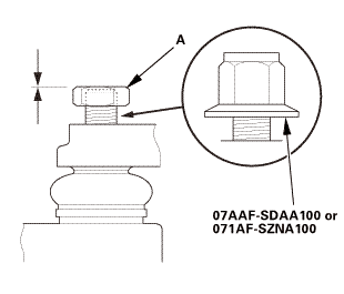
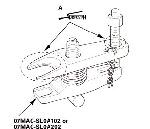
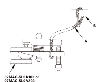
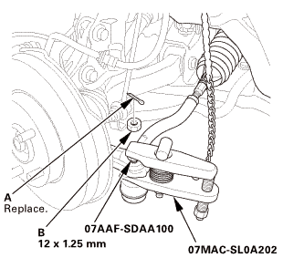
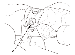
| 34. | Ball Joint - Removal |
|
|
Always use a ball joint remover to disconnect a ball joint. Do not strike the housing or any other part of the ball joint connection to disconnect it.
|
||||||

|
|
|
 ov
ov|
|
|
||||||||||||||||||||||||||||||||
 wmae-sldaidz
| 35. | Tie-Rod End Ball Joint - Disconnection, Both Side |
|
|
|
||||||||||||
 n7aaf-sdaainnmm
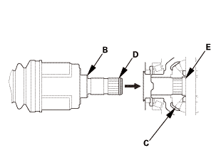
| 36. | Driveshaft Front Both - Disconnection Inboard Side |
|
|
|
|||||||||||||||||||||
|
|
|
||||||||||
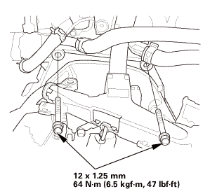
| 37. | Lower Torque Rod - Disconnection |
|
|
|
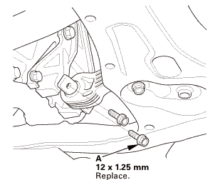
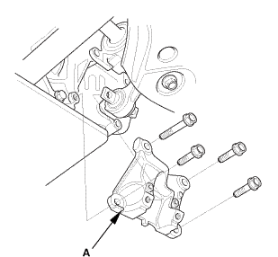
| 38. | Lower Torque Rod Bracket (Except K24Z7 Engine) |
|
|
|
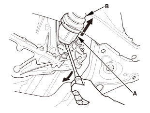
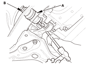
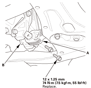
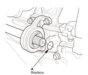
| 39. | Intermediate Shaft Assembly |
|
|
|
|
|
|
|
|
|
||||||
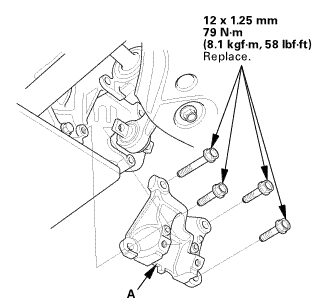
| 40. | Subframe Support |
|
|
|
| 41. | Front Subframe Assembly |
|
|
|
|
|
|
|
|
|
| 42. | Transmission Jack Support |
|
| 43. | M/T Assembly |
|
|
|
|
Front side
Rear side
|
|
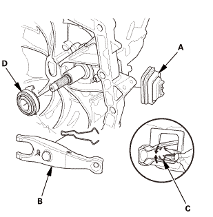
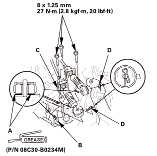
| 44. | Release Fork |
|
|
|
|
|
|
||||||
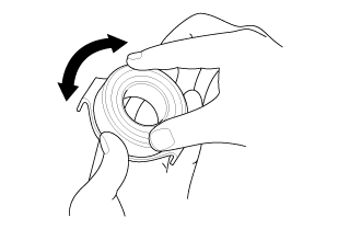

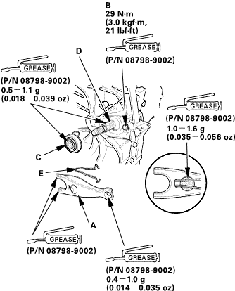
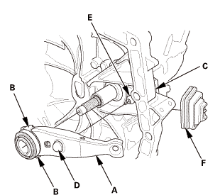
| 1. | Release Fork |
|
|
|
||||||||||||
 arm(u(p/m
|
|
|
|
|
|
||||||
| 2. | M/T Assembly |
|
|
|
|
Front side
Rear side
|
|
 i.z5mmonu....
|
|
|
 hlmm12m-mi12
| 3. | Intermediate Shaft Assembly |
|
|
|
||||||
|
|
|
 mmu....
|
|
|
 mms.
mms.| 4. | Subframe Support |
|
|
|
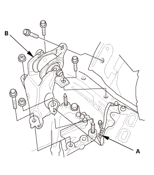
| 5. | Front Subframe Assembly |
|
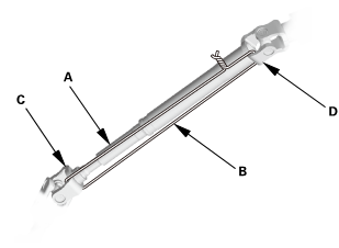
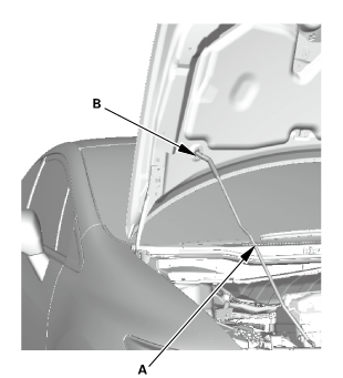
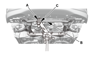
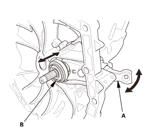
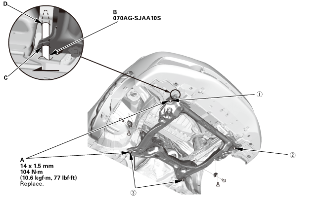
1. |
Loosely install the new front subframe mounting bolts (A). |
 o7oagsjaaosn-m77lm41!
|
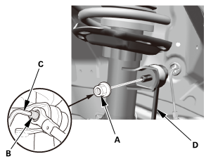
2. |
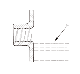
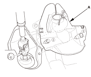
Insert the subframe alignment pin (B) through the positioning hole (C) on the right front subframe, and into the positioning hole (D) on the body, then loosely tighten the subframe right front mounting bolt. |
|
3. |
Insert the subframe alignment pin through the positioning slot on the left front subframe, and into the positioning hole on the body, then loosely tighten the subframe left front mounting bolt. |
|
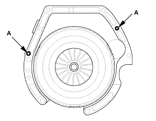
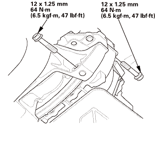
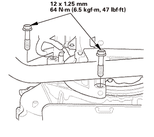
4. |
Tighten the subframe mounting bolts to the specified torque values starting with the right front subframe mounting bolt. Use the subframe alignment pin when tightening the front side subframe mounting bolts. |
|
5. |
Check all of the subframe mounting bolts, and retighten if necessary. |
|
|
NOTE: Tighten the bolts in the sequence shown. |
||
|
6. |
Remove the transmission jack and the subframe adapter. |
|
|
|
|
|
|
| 6. | Lower Torque Rod Bracket (Except K24Z7 Engine) |
|
|
|
 mmmn
mmmn| 7. | Lower Torque Rod - Reconnection |
|
|
|
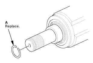
| 8. | Driveshaft Front Both - Reconnection Inboard Side |
|
|
|
|||||||||||||||||||
|
|
|
| 9. | Tie-Rod End Ball Joint - Connection, Both Side |
|
|
|
|||||||||||||||
| 10. | Front Stabilizer Ball Joint, Both Damper Side - Reconnection |
|
|
|
 125mmmm
| 11. | Lower Arm Joint - Reconnection, Both Knuckle Side |
|
|
|
 mm
mm| 12. | MTF Replacement |
|
|
|
||||||||||||||||||||||||||
| 13. | Engine Undercover |
|
|
|
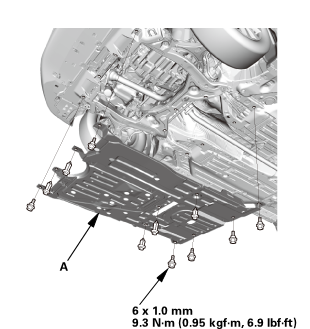 1.0mmmm
| 14. | Splash Shield |
|
1. |
Install the splash shield (A). |
| 15. | Front Wheel |
|
|
|
||||||
 mmmln-mnomm
| 16. | Lower The Vehicle On The Lift |
|
| 17. | Transmission Mount Assembly |
|
|
|
 mmi15imm15mm
| 18. | Upper Transmission Mounting Bolt |
|
|
|
 12mm
12mm| 19. | Steering Joint - Reconnection |
|
|
|
||||||||||||||||||||
|
|
|
| 20. | Steering Wheel Release |
|
|
|
| 21. | Steering Joint Bolt - Tighten |
|
|
|
 mm:.o21
| 22. | Steering Column Lower Slide Shaft - Release |
|
|
|
| 23. | Steering Joint Cover |
|
|
|
| 24. | Engine Support Hanger |
|
|
|
| 25. | Engine Support Hanger Peripheral Assembly |
|
|
|
| 26. | Engine Cover |
|
|
|
| 27. | Transmission Peripheral Assembly Upper Side |
|
|
|
| 28. | Shift Cable Bracket |
|
|
|
|||||||||||||||
| 29. | Slave Cylinder |
|
|
|
||||||||||||
 .25mmm.is
| 30. | Back-Up Light Switch Connector |
|
|
|
|
|
|
| 31. | Air Cleaner Bracket |
|
|
|
 in
in| 32. | ECM/PCM |
|
|
|
|||||||||
|
|
|
| 33. | Air Cleaner |
|
|
|
| 34. | Intake Air Pipe |
|
|
|
| 35. | Battery |
|
|
|
||||||
| 36. | Battery Terminal - Reconnection |
|
|
|
|||||||||||||||||||
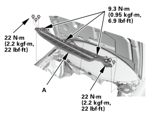
| 37. | Under Cowl Panel |
|
|
|
 22mm)2222
| 38. | Center Cowl Cover |
|
|
|
| 39. | Both Side Cowl Covers |
|
|
|
| 40. | Wiper Arm Assembly |
|
|
|
 1.122
1.122| 41. | Front Grille Cover |
|
|
|
|
|
|
| 42. | Manual Transmission After Install - Check |
|
| 43. | Pre-Alignment Checks |
|
| 44. | Caster - Inspection |
|
|||||||||||||||||||||||||||||||||||||||||||||||
| 45. | Camber - Inspection |
|
||||||||||||||||||||||||||||||||||||||||||||||||||||||||||||||||||||||||||||||||||||||
| 46. | Front Toe - Inspection |
|
|||||||||||||||||||||||||
| 47. | Turning Angle - Inspection |
|
|
|
|||||||||||||||||||||||||||||||||||||||||||||||||||||||||||||||||||||||||||||||||||||||||
|
|
|
|||||||||||||||||||||||||||||||||||||||||||||||||||||||||
| 48. | HDS DLC - Connection |
|
|
|
| 49. | VSA Sensor Neutral Position - Memorization |
|
||||||||||
| 50. | Steering Angle Sensor Neutral Position - Clear |
|
|||||||
| 51. | Maintenance Minder Reset |
|
 Manual Transmission Removal and Installation (K24Z7)
2131K5
1.
Steering Joint Cover
1.
Remove the steering joint cover (A).
2. ...
 Right M/T Differential Oil Seal Replacement (R18Z1 M/T)
2191F5 RIGHT
1.
Vehicle Lift
1.
Raise the vehicle on a lift, and make sure it is securely supported.
...
See also:
Honda Civic Service Manual. Rear Air Outlet Removal and Installation
8411A4
Removal
1.
Rear Bumper
1.
Remove the screws (A), the bolts (B), and the clips (C,
D) securing the rear bumper (E).
...
