Honda Civic Service Manual: M/T Shift Cable Removal and Installation (R18Z1 M/T)
212150

|
SRS components are located in this area. Review the SRS Component Location
Index and the SRS Precautions and Procedures before doing repair or service.
|
|
|
|
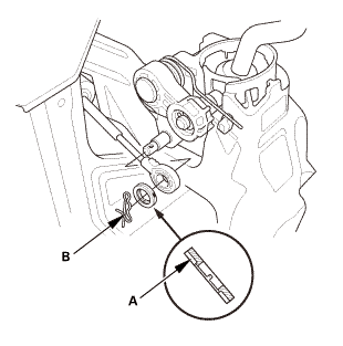
1.
|
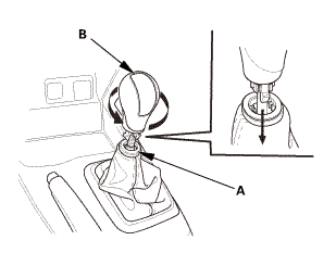
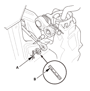
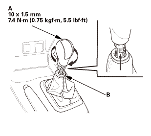
Lower the shift lever boot (A) to release the hooks from the
boot.
|
|
2.
|
Remove the shift lever knob (B).
|
|
|
|
|
2.
|
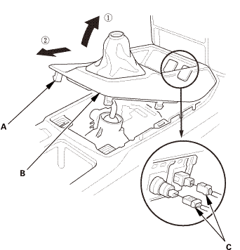
Remove the center console panel (B).
|
|
3.
|
For some models: Disconnect the connector(s) (C).
|
|
| 3. |
Cup Holder Panel Assembly |
|
|
|
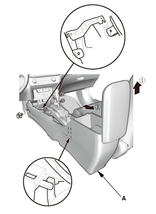
1.
|
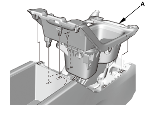
Remove the cup holder panel assembly (A).
|
|
|
|
|
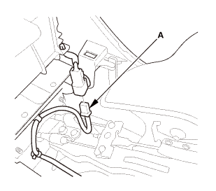
2.
|
Disconnect the connector (B).
|
|
|
|
|
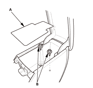
3.
|
Remove the console box mat (A).
|
|
|
|
|
5.
|
Disconnect the connector (A).
|
|
|
|
|
6.
|
Remove the center console (A).
|
|
| 5. |
M/T Shift Lever Assembly |
|
|
|
1.
|
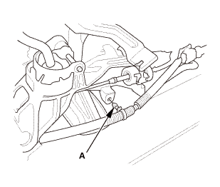
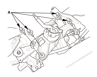
Remove the harness clamp (A).
|
|
|
|
|
2.
|
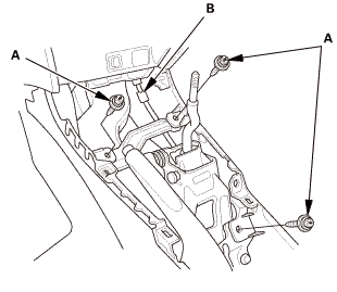
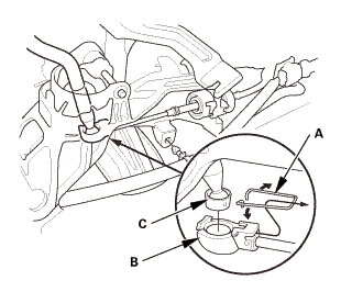
Remove the lock pin (A).
|
|
3.
|
Remove the washer (B).
|
|
|
|
|
5.
|
Disconnect the shift cable (B) from the shift lever (C).
|
|
|
|
|
6.
|
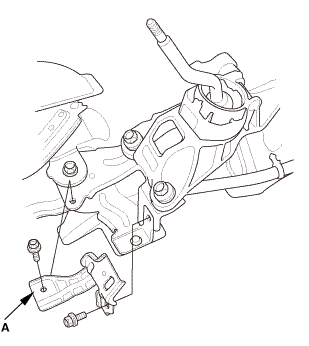
Remove the bracket (A).
|
|
|
|
|
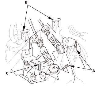
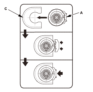
8.
|
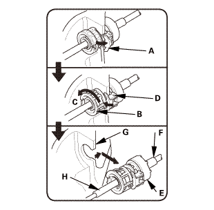
Unlock the retainer lock (A).
|
|
9.
|
Rotate the socket holder retainer (B) counterclockwise (C) until
it stops, and push the retainer lock (D) into the socket holder
retainer to lock the retainer.
|
|
10.
|
Slide the socket holder (E) and the shift cable (F) out of the
shift cable bracket (G).
|
|
NOTE: Do not remove the shift cable by pulling the shift cable
guide (H).
|
|
|
|
|
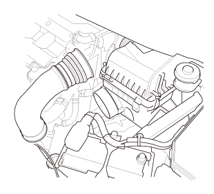
1.
|
Remove the intake air pipe.
|
|
|
|
|
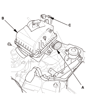
1.
|
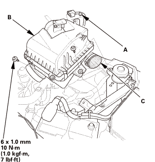
Disconnect the intake air duct (A).
|
|
2.
|
Remove the air cleaner (B).
|
|
3.
|
Remove the harness clamp (C).
|
|
| 8. |
Back-Up Light Switch Connector |
|
|
|
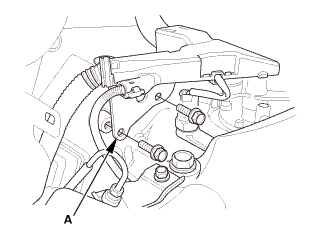
1.
|
Remove the transmission hanger (A).
|
|
|
|
|
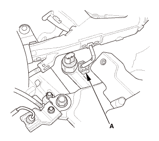
2.
|
Disconnect the connector (A).
|
|
|
|
|
1.
|
Remove the lock pins (A).
|
|
2.
|
Remove the shift cable clips (B).
|
|
3.
|
Disconnect the shift cables from the change lever assembly (C).
|
|
|
|
1.
|
Raise the vehicle on a lift, and make sure it is securely supported.
|
|
|
|
|
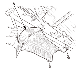
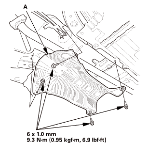
1.
|
Remove the heat shield (A).
|
|
|
|
|
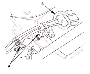
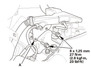
2.
|
Remove the shift cable brackets (A).
|
|
3.
|
Remove the shift cable grommet (B), and pull out the shift cables.
|
|
NOTE: Do not bend the shift cable excessively.
|
|

|
SRS components are located in this area. Review the SRS Component Location
Index and the SRS Precautions and Procedures before doing repair or service.
|
|
|
|
1.
|
Insert the shift cables through the grommet hole (A).
|
|
NOTE: Do not bend the shift cable excessively.
|
|
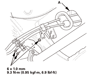
2.
|
Install the shift cable grommet in its hole.
|
|
3.
|
Install the shift cable brackets.
|
|
|
|
|
4.
|
Install the heat shield (A).
|
|
|
 (pm (pm
|
|
1.
|
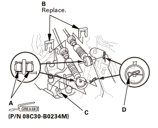
Apply a light coat of silicone grease (P/N 08C30- B0234M) to
the shift cable ends (A).
|
|
NOTE: Make sure not to get any silicone grease on the terminal
part of the connectors and switches, especially if you have silicone
grease on your hands or gloves.
|
|
2.
|
Install a new shift cable clips (B).
|
|
3.
|
Connect the shift cable ends to the change lever assembly (C).
|
|
4.
|
Install the lock pins (D).
|
|
| 3. |
Back-Up Light Switch Connector |
|
|
|
1.
|
Connect the connector (A).
|
|
|
|
|
2.
|
Install the transmission hanger (A).
|
|
|
|
|
1.
|
Install the harness clamp (A).
|
|
2.
|
Install the air cleaner (B).
|
|
3.
|
Connect the intake air duct (C).
|
|
|
|
|
1.
|
Install the intake air pipe.
|
|
| 6. |
M/T Shift Lever Assembly |
|
|
|
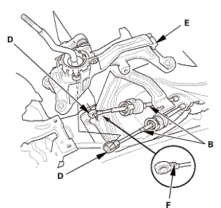
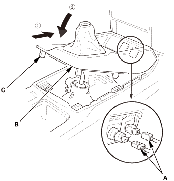
1.
|
Align the socket holder (A) on the shift cables (B) with the
slot in the bracket base (C).
|
|
2.
|
Slide the socket holder into the bracket base.
|
|
3.
|
Install the shift cable ends (D) to the shift lever assembly
(E).
|
|
NOTE: When installing the shift cable (shift lever side), position
the serrated side (F) facing up.
|
|
|
|
|
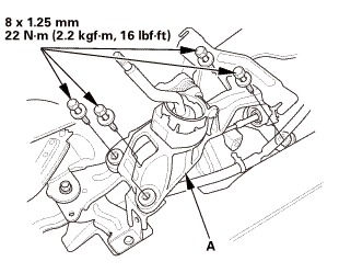
4.
|
Install the shift lever assembly (A).
|
|
|
|
|
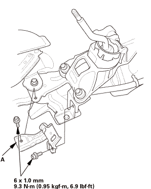
5.
|
Install the bracket (A).
|
|
|
|
|
6.
|
Install the washer (A).
|
|
7.
|
Install the lock pin (B).
|
|
|
|
|
8.
|
Install the harness clamp (A).
|
|
|

|
|
1.
|
Install the center console (A).
|
|
|
|
|
2.
|
Connect the connector (A).
|
|
|
|
|
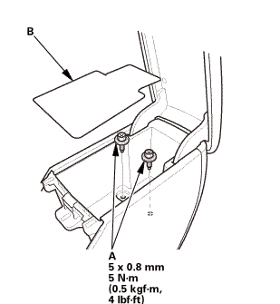
3.
|
Install the bolts (A).
|
|
4.
|
Install the console box mat (B).
|
|
|
|
|
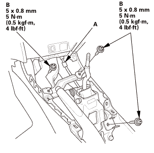
5.
|
Connect the connector (A).
|
|
6.
|
Install the bolts (B).
|
|
| 8. |
Cup Holder Panel Assembly |
|
|
|
1.
|
Install the cup holder panel assembly (A).
|
|
|
|
|
1.
|
For some models: Connect the connector(s) (A).
|
|
2.
|
Install the center console panel (B).
|
|
3.
|
Install the clips (C).
|
|
|
|
|
1.
|
Install the shift lever knob (A).
|
|
NOTE: Tighten the shift lever knob until the shift pattern is
properly aligned.
|
|
2.
|
Connect the shift lever boot (B).
|
|
210101
Removal
1.
Pressure Plate
1.
Install the ring gear holder.
...
2321H3
1.
Vehicle Lift
1.
Raise the vehicle on a lift, and make sure it is securely supported.
...
 Flywheel Removal and Installation (R18Z1 M/T)
 Transmission End Cover Selector Control Shaft Oil Seal Replacement (A/T)