Honda Civic Service Manual: M/T Countershaft Disassembly, Reassembly, and Inspection (K24Z7)
 Disassembly
|
NOTE: Refer to the Exploded View as needed during this procedure. |
| 1. | M/T Change Lever Assembly |
|
|
|
| 2. | Back-Up Light Switch |
|
|
|
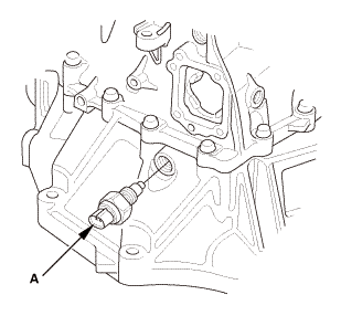
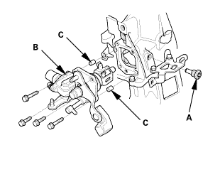
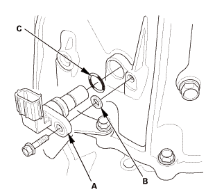
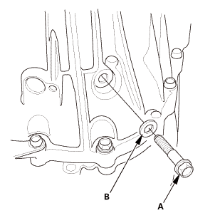
| 3. | Output Shaft (Countershaft) Speed Sensor |
|
|
|
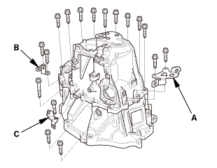
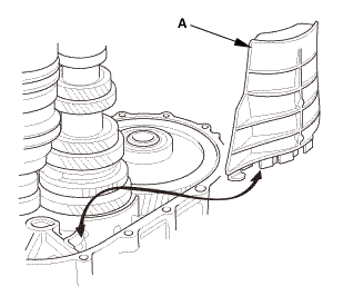
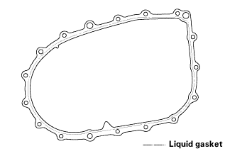
| 4. | Transmission Housing |
|
|
|
|
|
|
|
|
|
|
|
|
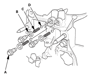
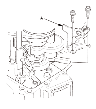
| 5. | Reverse Shift Fork |
|
|
|
| 6. | Baffle Plate |
|
|
|
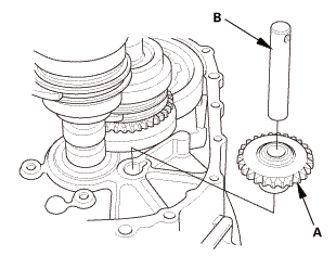
| 7. | Reverse Idler Gear |
|
|
|
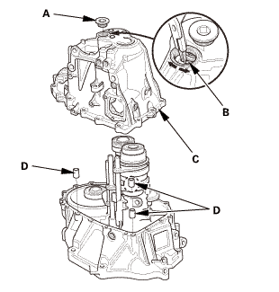
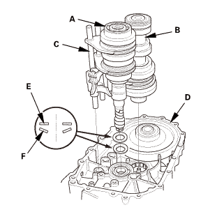
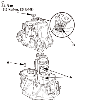
| 8. | M/T Mainshaft and Countershaft and Shift Fork Assembly |
|
|
|
|||||||||||||||
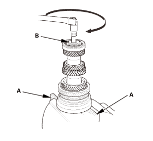
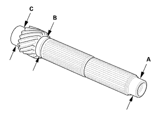
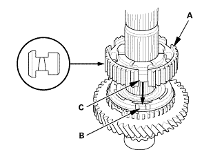
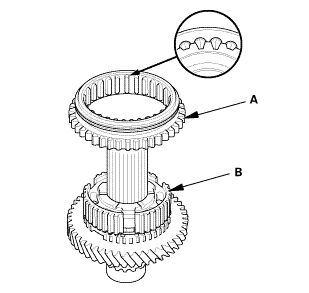
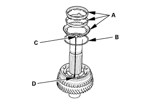
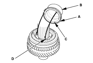
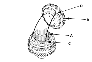
| 9. | M/T Countershaft |
|
|
|
|
|
|
|
|
|
|
|
|
 Inspection
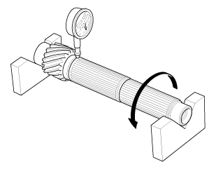
| 1. | M/T Countershaft Inspection |
|
|
|
||||||||||||||||||||||||||||||||||
|
|
|
|||||||||||||
 View
View
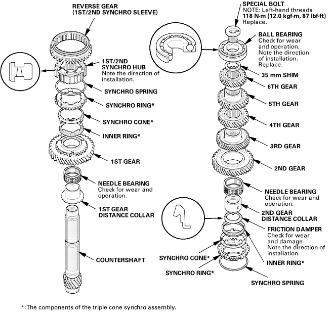
| 1. | M/T Countershaft Exploded View |
|
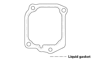
Exploded View |
 umuzreplaceandmsahahunmmnom:(aha(mnspringgeargearavvddamagsdwemmvat
 Reassembly
|
NOTE: Refer to the Exploded View as needed during this procedure. |
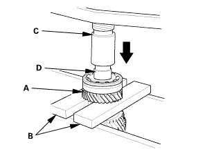
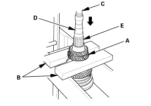
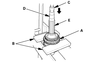
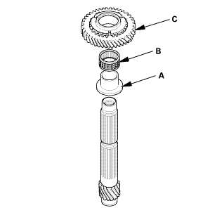
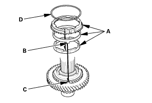
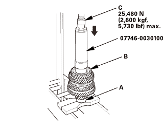
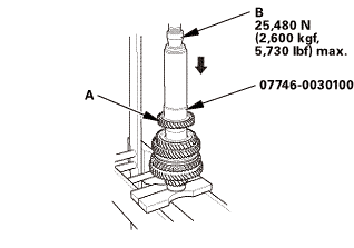
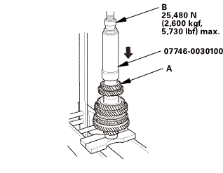
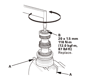
| 1. | M/T Countershaft |
|
|
|
|
|
|
|
|
|
|
|
|
|||||||||
|
|
|
|
|
|
|
|
|
|
|
|
|||||||||
 sun
sun|
|
|
||||||
 s,m
s,m|
|
|
||||||
 (2,snn
|
|
|
||||||
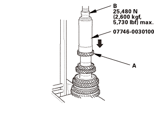 zs,4ioums.uuau1uu
|
|
|
||||||||||||||||||||
 nms.nn:mnn
|
|
|
||||||||||||||||||||||||||||||||||||||||||||||||||||||||||||||||||||||||||||||
|
|
|
|
|
|
||||||
|
|
|
|||||||||||||||
 nms.nu:n1nn
|
|
|
|||||||||
 mm(noumn
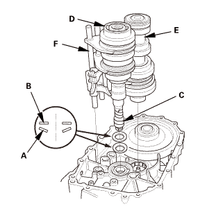
| 2. | M/T Mainshaft and Countershaft and Shift Fork Assembly |
|
|
|
||||||||||||||||||
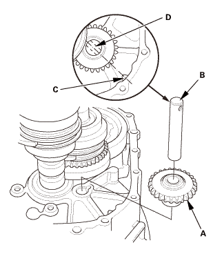
| 3. | Reverse Idler Gear |
|
|
|
| 4. | Baffle Plate |
|
|
|
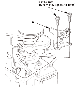
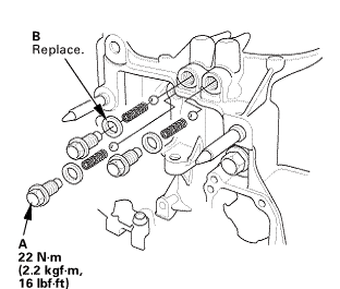
| 5. | Reverse Shift Fork |
|
|
|
 mmlbf!
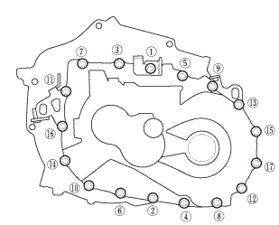
| 6. | Transmission Housing |
|
|
|
||||||||||||||||||||
|
|
|
|||||||||||||||
|
|
|
|||||||||||||||||||||||
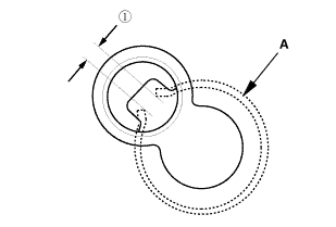
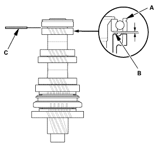
 as installed:
3.3-6.0 mm (0.130-0.236 in)
as installed:
3.3-6.0 mm (0.130-0.236 in)|
|
|
|
|
|
||||||||||
|
|
|
|
|
|
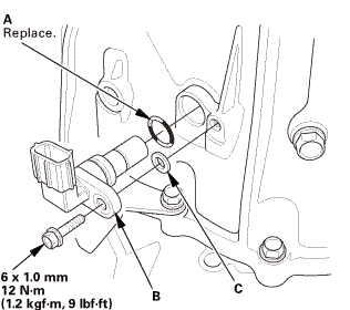
| 7. | Output Shaft (Countershaft) Speed Sensor |
|
|
|
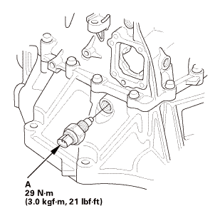
| 8. | Back-Up Light Switch |
|
|
|
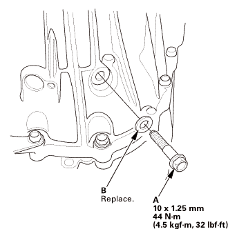
| 9. | M/T Change Lever Assembly |
|
|
|
||||||||||||||||||||
 iukn
iukn|
|
|
 M/T Countershaft Bearing Replacement (R18Z1 M/T)
Removal
1.
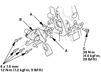
M/T Change Lever Assembly
1.
Remove the change lever assembly (A).
...
 M/T Mainshaft Assembly Clearance Inspection (K24Z7)
Removal
1.
M/T Change Lever Assembly
1.
Remove the interlock bolt (A).
...
See also:
Honda Civic Owners Manual. Rear Seat Heaters
The power mode must be in ON to use the
seat heaters.
There is no heater in the rear center seating
position.
The indicator for your setting comes on while
the seat heater is in use. Press the button on
the opposite side to turn the heater off. The
indicator goes off.
While in HI, ...
