Honda Civic Service Manual: M/T Countershaft Bearing Replacement (R18Z1 M/T)

Removal
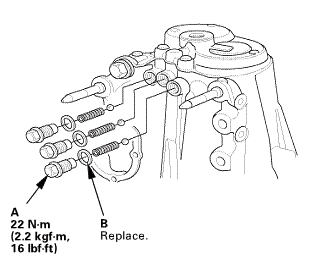
| 1. | M/T Change Lever Assembly |
|
|
|
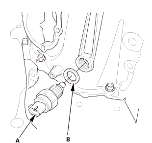
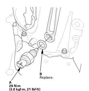
| 2. | Back Up Light Switch |
|
|
|
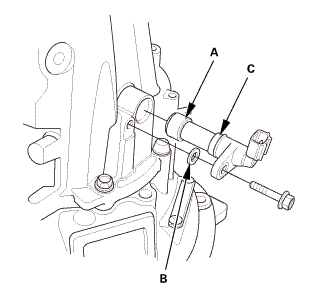
| 3. | M/T Output Shaft Speed Sensor |
|
|
|
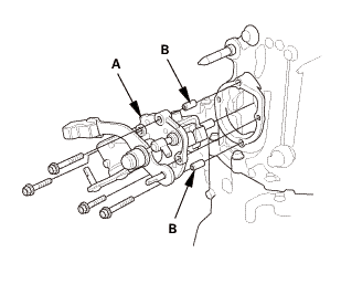
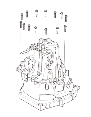
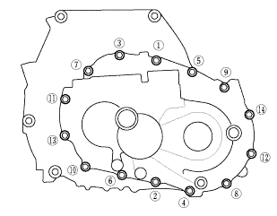
| 4. | M/T Transmission Housing Assembly |
|
|
|
|
|
|
|
|
|
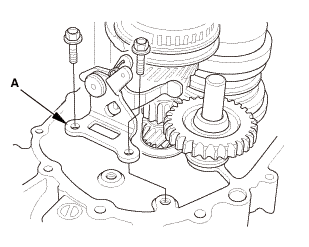
| 5. | M/T Reverse Shift Fork |
|
|
|
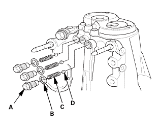
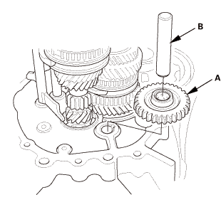
| 6. | Reverse Idler Gear |
|
|
|
| 7. | M/T Mainshaft and Countershaft and Shift Fork Assembly |
|
|
|
|||||||||||||||
| 8. | Differential Assembly |
|
|
|
| 9. | M/T Clutch Housing Countershaft Bearing |
|
|
|

Installation
| 1. | M/T Clutch Housing Countershaft Bearing |
|
|
|
| 2. | Differential Assembly |
|
|
|
|||||||||

| 3. | M/T Mainshaft and Countershaft and Shift Fork Assembly |
|
|
|
||||||||||||||||||
| 4. | Reverse Idler Gear |
|
|
|
| 5. | M/T Reverse Shift Fork |
|
|
|
| 6. | M/T Transmission Housing Assembly |
|
|
|
||||||||||||||||||||

|
|
|
||||||||||||||||||
 imto
imto|
|
|
|||||||||||||||||||||||
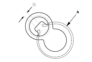
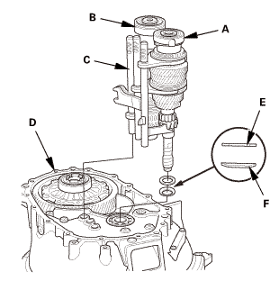
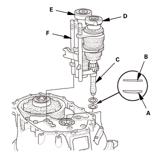
 as installed:
3.3-6.5 mm (0.130-0.256 in)
as installed:
3.3-6.5 mm (0.130-0.256 in)|
|
|
|
|
|
||||||||||
|
|
|
 2215
2215| 7. | M/T Output Shaft Speed Sensor |
|
|
|
| 8. | Back Up Light Switch |
|
|
|
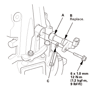
| 9. | M/T Change Lever Assembly |
|
|
|
||||||||||||||||||||
 -mid
-mid|
|
|
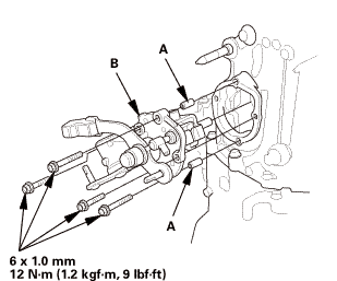 .omm-m(i.2kvf-m.9bm1!
 M/T Countershaft Bearing Replacement (K24Z7)
2131F8
Removal
1.
M/T Change Lever Assembly
1.
Remove the interlock bolt (A).
...
 M/T Countershaft Disassembly, Reassembly, and Inspection (K24Z7)
Disassembly
NOTE: Refer to the Exploded View as needed during this procedure.
1.
M/T Change Lever Assembly
...
See also:
Honda Civic Owners Manual. Limitations for Manual Operation
Certain manual functions are disabled or inoperable while the vehicle is in
motion.
You cannot select a grayed-out option until the vehicle is stopped.
Only previously stored speed dial entries can be called using voice commands
while
the vehicle is in motion.
HFL Status Displ ...
