Honda Civic Service Manual: Carpet Removal and Installation (2-door A/T)
847100

|
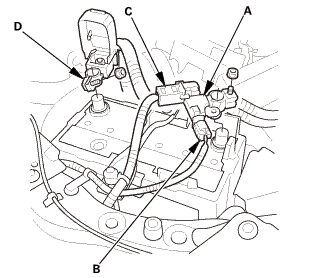
SRS components are located in this area. Review the SRS component locations and the precautions and procedures before doing repairs or service. |
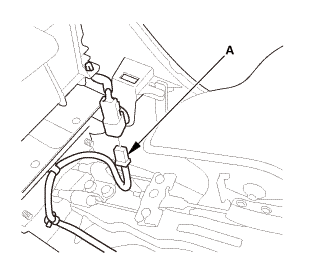
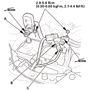
| 1. | Battery Terminal (SRS) - Disconnection |
|
|
|
||||||||||||||||||||||||||||||

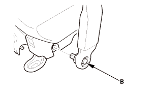
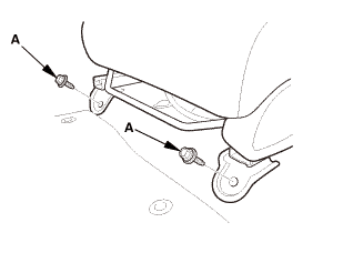
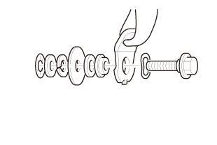
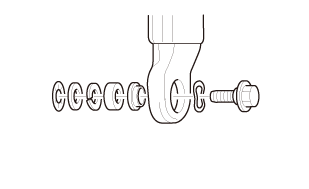
| 2. | Both Front Seat Belt Lower Anchor Bolts |
|
Driver's side
Passenger's side
|
|
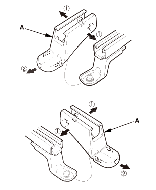
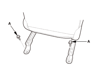
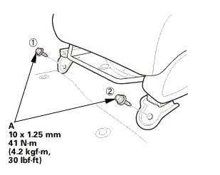
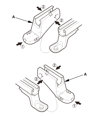
| 3. | Both Front Seats |
|
|
|
|
Front side
Rear side
|
|
|
|
|
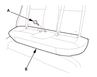
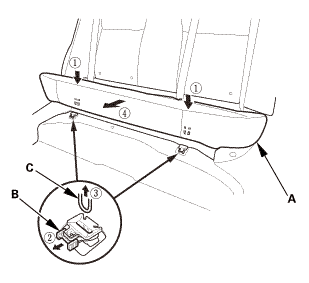
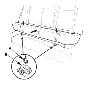
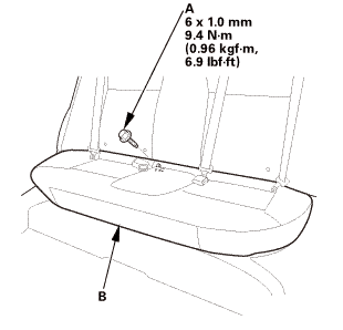
| 4. | Rear Seat Cushion |
|
|
|
|
|
|
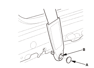
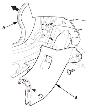
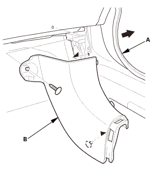
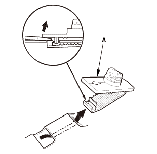
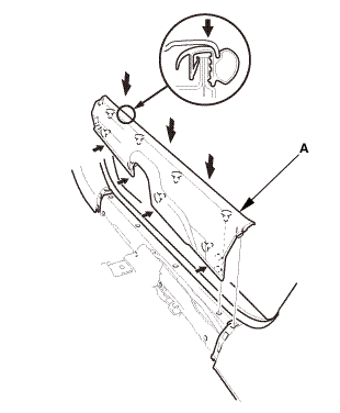
| 5. | Front Door Sill Trim - 2-Door |
|
|
|
|
|
|
|
|
|
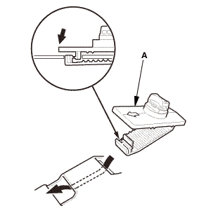
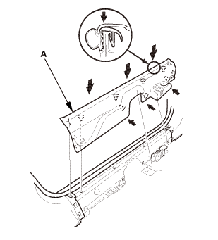
| 6. | Front Door Sill Trim - 2-Door |
|
|
|
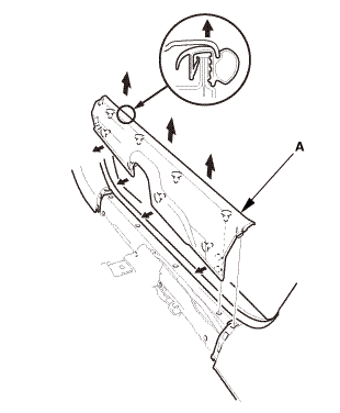
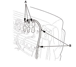
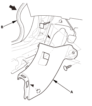
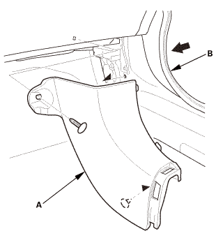
| 7. | Both Kick Panels |
|
Driver's side
Passenger's side
|
|
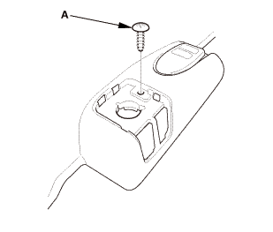
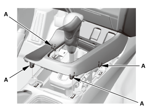
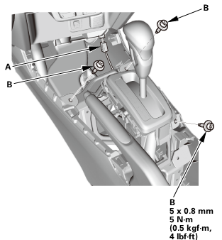
| 8. | Center Console Panel Assembly (Except '12M M/T) |
|
|
|
|
|
|
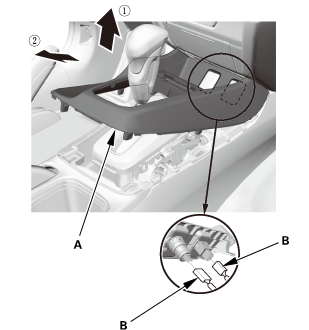
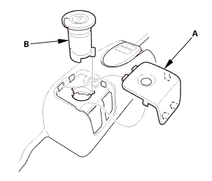
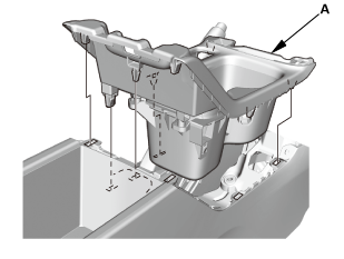
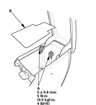
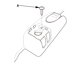
| 9. | Cup Holder Panel Assembly |
|
|
|
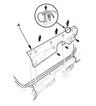
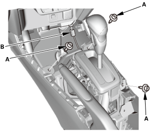
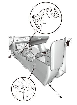
| 10. | Center Console |
|
|
|
|
|
|
|
|
|
|
|
|
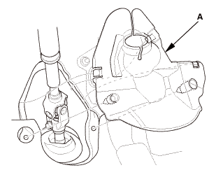
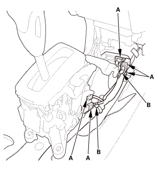
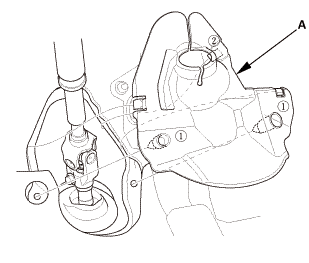
| 11. | Steering Joint Cover |
|
|
|
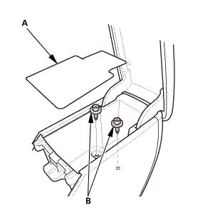
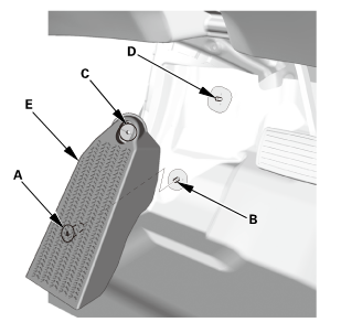
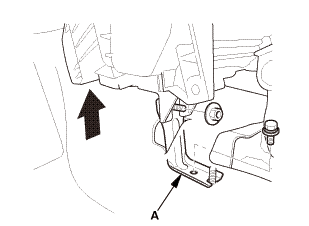
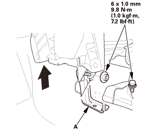
| 12. | Footrest |
|
|
|
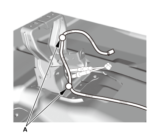
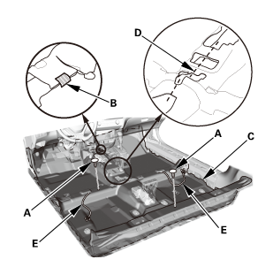
| 13. | Floor Carpet - 2-Door (A/T) |
|
|
|
|
|
|
|
|
|
|
|
|
|
|
|

|
SRS components are located in this area. Review the SRS component locations and the precautions and procedures before doing repairs or service. |
| 1. | Floor Carpet - 2-Door (A/T) |
|
|
|
|
|
|

|
|
|
|
|
|
|
|
|
| 2. | Footrest |
|
|
|

| 3. | Steering Joint Cover |
|
|
|
| 4. | Center Console |
|
|
|

|
|
|
|
|
|
|
|
|
| 5. | Cup Holder Panel Assembly |
|
|
|
| 6. | Center Console Panel Assembly (Except '12M M/T) |
|
|
|

|
|
|
| 7. | Both Kick Panels |
|
Driver's side
Passenger's side
|
|
| 8. | Front Door Sill Trim - 2-Door |
|
|
|
| 9. | Front Door Sill Trim - 2-Door |
|
|
|
|
|
|
|
|
|

| 10. | Rear Seat Cushion |
|
|
|
|
|
|
| 11. | Both Front Seats |
|
|
|
|
Front side
Rear side
|
|
||||||||||||||||||||
 1n25mman
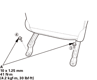
|
|
|
| 12. | Both Front Seat Belt Lower Anchor Bolts |
|
Driver's side
Passenger's side
|
|
||||||
 @@@
@@@|
Driver's side
Passenger's side
|
|
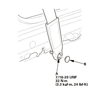 7m2nmn:mm
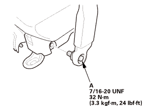 unr:2inm,
| 13. | Battery Terminal (SRS) - Reconnection |
|
|
|
|||||||||||||||||||
 (o.2ao.sam.
 Carpet Removal and Installation (4-door A/T)
847100
SRS components are located in this area. Review the SRS component locations
and the precautions and procedures before doing repairs or service.
1.
Bat ...
See also:
Honda Civic Owners Manual. Voice Portal Screen
When the (Talk) button is
pressed,
available voice commands appear on the
screen.
For a complete list of commands, say ’Voice
Help’ after the beep or select Voice Help.
You can see the list of commands in Voice
Info on the Info menu screen. Select Info,
then select .
T ...
