Honda Civic Service Manual: Brake Pedal and Brake Pedal Position Switch Adjustment

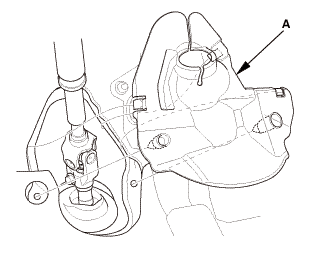
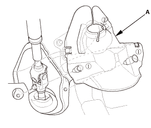
| 1. | Steering Joint Cover |
|
|
|
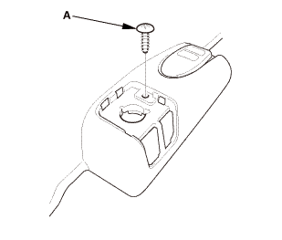
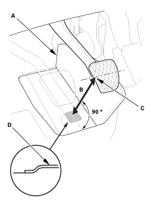
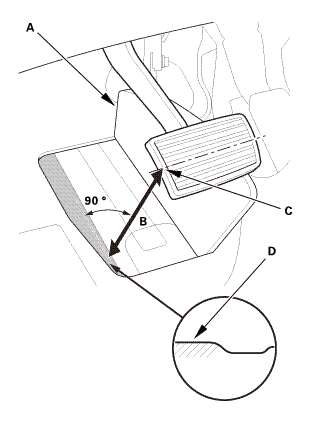
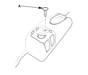
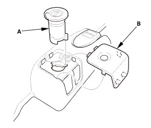
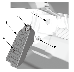
| 2. | Footrest |
|
|
|

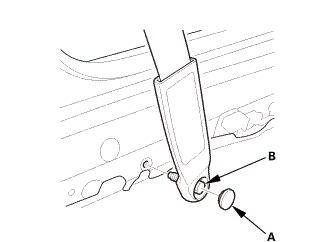
| 3. | Front Seat Belt Lower Anchor Bolt - 2-Door |
|
|
|
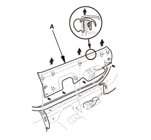
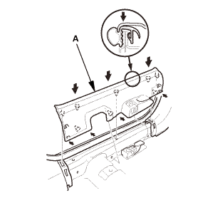
| 4. | Front Door Sill Trim - 2-Door |
|
|
|

|
|
|
|
|
|
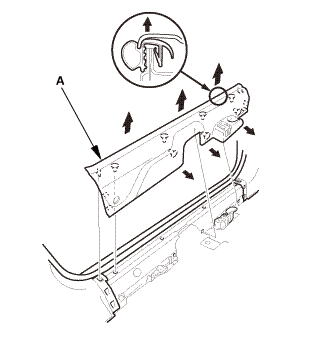
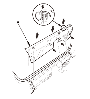
| 5. | Front Door Sill Trim - 4-Door |
|
|
|
|
|
|
|
|
|
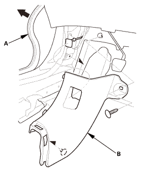
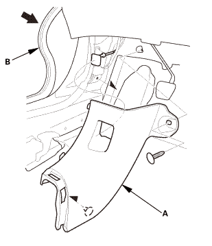
| 6. | Kick Panel |
|
|
|

| 1. | Brake Pedal Height - Inspection |
|
M/T
A/T
|
|
|||||||||||||||||||||||||||||||

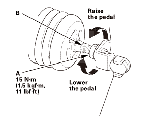
| 1. | Brake Pedal - Adjustment |
|
|
|

|
|
|
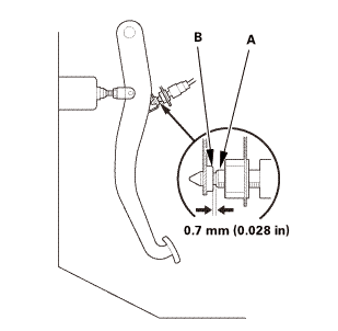
| 2. | Brake Pedal Position Switch - Adjustment |
|
|
|
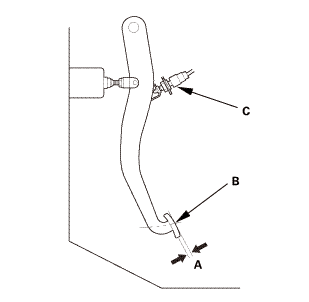
| 3. | Brake Pedal Free Play - Check |
|
|
|
|||||||||

| 1. | Kick Panel |
|
|
|
| 2. | Front Door Sill Trim - 4-Door |
|
|
|
|
|
|
|
|
|
| 3. | Front Door Sill Trim - 2-Door |
|
|
|
|
|
|
|
|
|
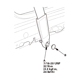
| 4. | Front Seat Belt Lower Anchor Bolt - 2-Door |
|
|
|
||||||
 @@@
@@@|
|
|
 7/1s-2om-min
| 5. | Footrest |
|
|
|
| 6. | Steering Joint Cover |
|
|
|
 Brake Pedal Removal and Installation
4101B1
1.
Steering Joint Cover
1.
Remove the steering joint cover (A).
2.
...
 Parking Brake
...
See also:
Honda Civic Service Manual. Keyless Access LF Antenna (Rear Interior) Removal and Installation
1.
Rear Interior LF Antenna
1.
Open the trunk lid.
2.
Remove the rear interior LF antenna (A).
...
