Honda Civic Service Manual: M/T Mainshaft Thrust Clearance Adjustment (K24Z7)

Removal
| 1. | M/T Change Lever Assembly |
|
|
|
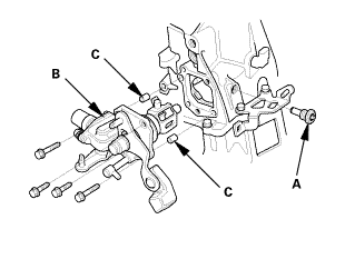
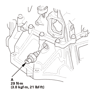
| 2. | Back-Up Light Switch |
|
|
|
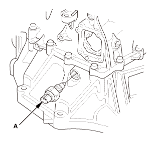
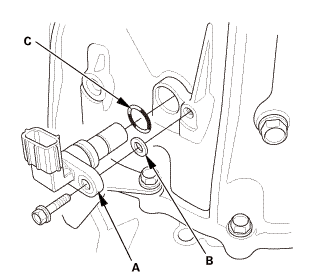
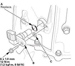
| 3. | Output Shaft (Countershaft) Speed Sensor |
|
|
|
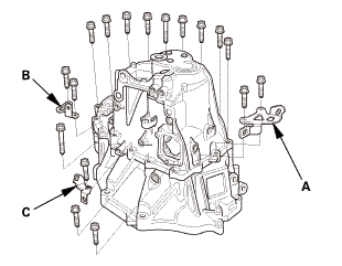
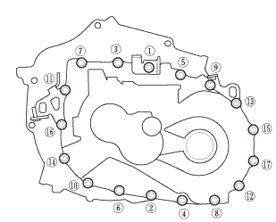
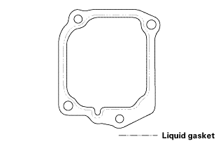
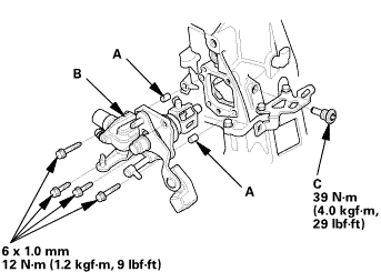
| 4. | Transmission Housing |
|
|
|
|
|
|
|
|
|
|
|
|
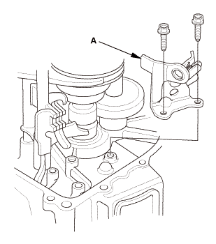
| 5. | Reverse Shift Fork |
|
|
|
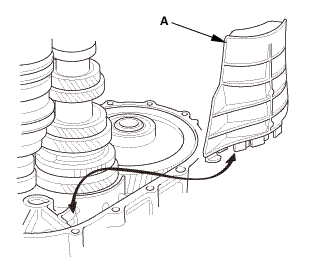
| 6. | Baffle Plate |
|
|
|
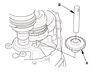
| 7. | Reverse Idler Gear |
|
|
|
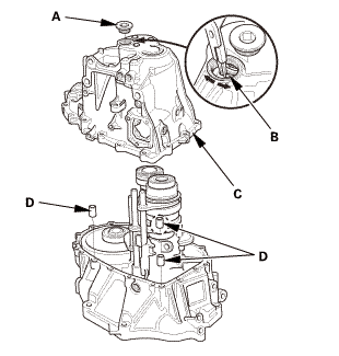
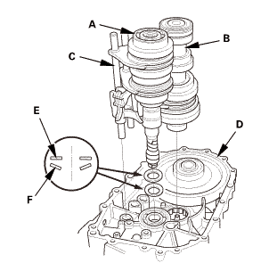
| 8. | M/T Mainshaft and Countershaft and Shift Fork Assembly |
|
|
|
|||||||||||||||
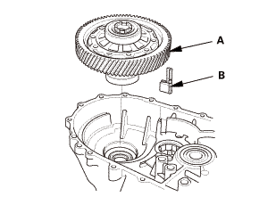
| 9. | Differential Assembly |
|
|
|
 Adjustment
| 1. | M/T Mainshaft Thrust Clearance Adjustment |
|
|
|
|||||||||||||||||||||||||||
|
|
|
||||||||||||||||||||||||

|
|
|
|||||||||||||||||||||||||||||||||||||||||||||||||||||||||||||||||||||||||||||||||||||||||||||||||||||||||||||||||||||||||||||||||||||||||||||||||||||||||||||||||||

Installation
| 1. | Differential Assembly |
|
|
|
|||||||||

| 2. | M/T Mainshaft and Countershaft and Shift Fork Assembly |
|
|
|
||||||||||||||||||
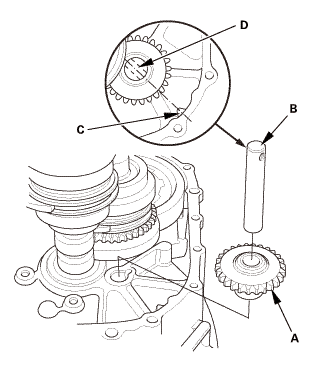
| 3. | Reverse Idler Gear |
|
|
|
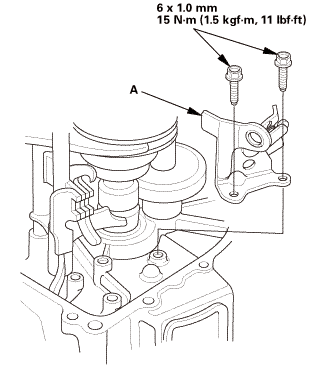
| 4. | Baffle Plate |
|
|
|
| 5. | Reverse Shift Fork |
|
|
|
 mmlbf!
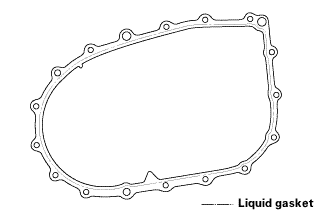
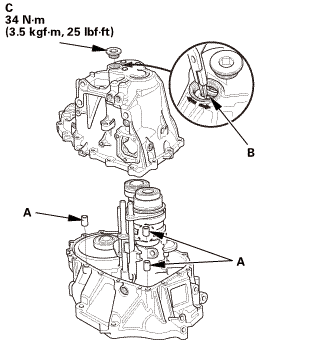
| 6. | Transmission Housing |
|
|
|
||||||||||||||||||||
|
|
|
|||||||||||||||
|
|
|
|||||||||||||||||||||||
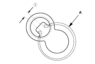
 as installed:
3.3-6.0 mm (0.130-0.236 in)
as installed:
3.3-6.0 mm (0.130-0.236 in)|
|
|
|
|
|
||||||||||
|
|
|
|
|
|
| 7. | Output Shaft (Countershaft) Speed Sensor |
|
|
|
| 8. | Back-Up Light Switch |
|
|
|
| 9. | M/T Change Lever Assembly |
|
|
|
||||||||||||||||||||
 iukn
iukn|
|
|
 M/T Mainshaft Disassembly, Reassembly, and Inspection (R18Z1 M/T)
Disassembly
NOTE: Refer to the Exploded View as needed during this procedure.
1.
M/T Change Lever Assembly
...
 M/T Reverse Shift Fork Clearance Inspection (K24Z7)
Removal
1.
M/T Change Lever Assembly
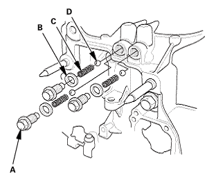
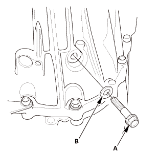
1.
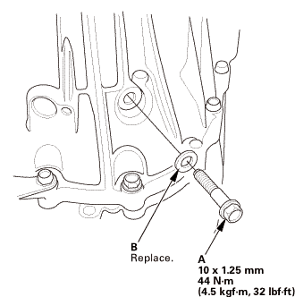
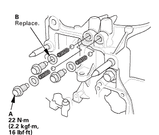
Remove the interlock bolt (A).
...
See also:
Honda Civic Owners Manual. Cruise Control
Maintains a constant vehicle speed without having to keep your foot on the
accelerator. Use cruise control on freeways or open roads where you can travel
at a
constant speed with little acceleration or deceleration.
*1: Models with information display
*2: Models with driver information int ...
