Honda Civic Service Manual: Steering Lock Removal and Installation

|
SRS components are located in this area. Review the SRS component locations, and the precautions and procedures before doing repairs or service. |
| 1. | Battery Terminal (SRS) - Disconnection |
|
|
|
||||||||||||||||||||||||||||||

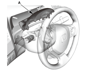
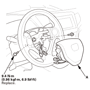
| 2. | Driver's Airbag |
|
|
|
|
|
|
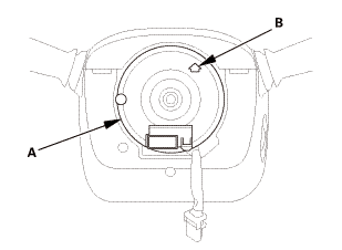
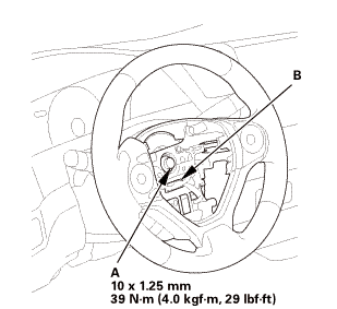
| 3. | Steering Wheel Assembly |
|
|
|
 wxusmm
|
|
|
||||||||||||||||||||
|
|
|
| 4. | Upper Column Cover |
|
|
|

| 5. | Lower Column Cover |
|
|
|
|
|
|
| 6. | Combination Switch Body Assembly |
|
|
|
|
|
|
|
Without steering lock
With steering lock
|
|
| 7. | Immobilizer-Keyless Control Unit |
|
|
|
| 8. | Steering Joint Cover |
|
|
|
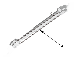
| 9. | Steering Column Lower Slide Shaft - Hold |
|
|
|
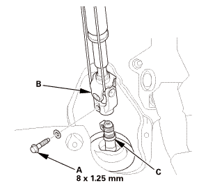
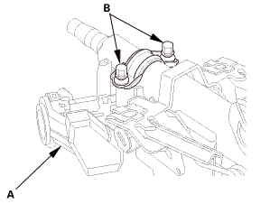
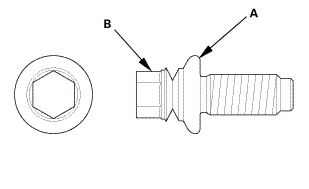
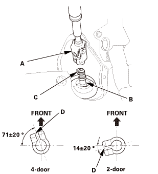
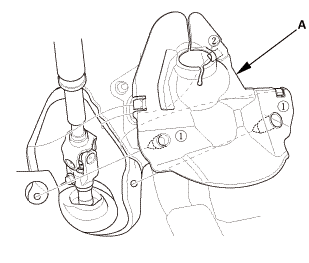
| 10. | Steering Joint Bolt - Loosen |
|
|
|
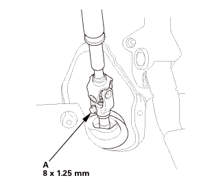
| 11. | Steering Joint - Disconnection |
|
|
|
||||||||||||||||||||
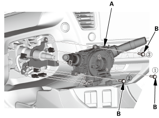
| 12. | Steering Column |
|
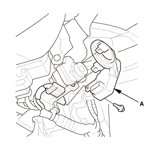
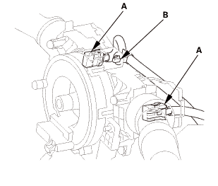
1. |
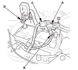
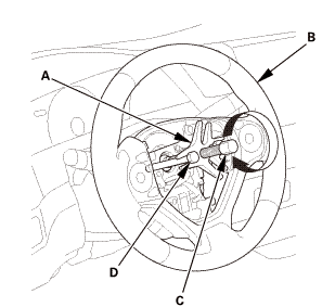
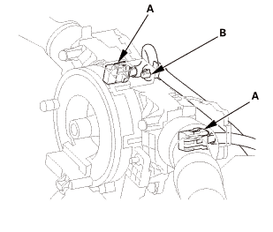
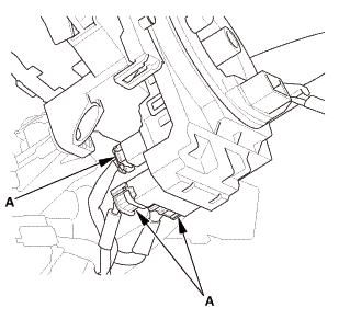
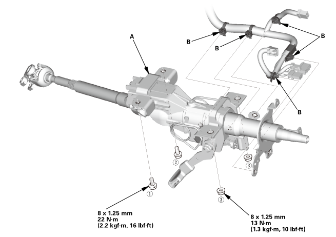
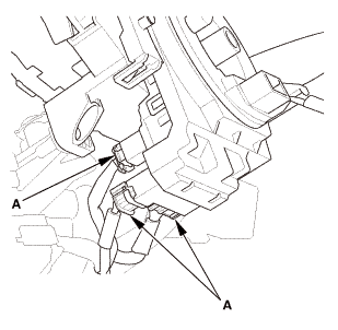
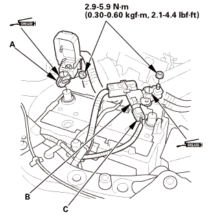
With steering lock: Disconnect the connectors (A) from the ignition switch (B). |
Without steering lock
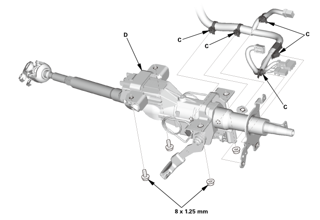
With steering lock
|
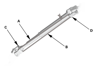
2. |
Detach the wire harness clips (C) from the steering column. |
|
3. |
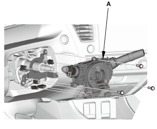
Remove the steering column (D). |
|
|
NOTE: Do not release the lock lever until the steering column is installed. If the lock lever is released before installation, adjust the steering column after installation. |
||
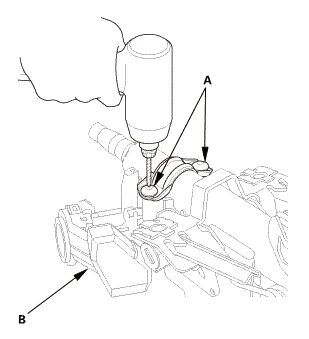
| 13. | Steering Lock Assembly |
|
|
|
||||||||||||

|
SRS components are located in this area. Review the SRS component locations, and the precautions and procedures before doing repairs or service. |
|
NOTE: If you replace the keyless access control unit or the steering lock (has a built-in electric steering lock control unit), the vehicle is not turned to the ON mode. Follow the registration procedure of the corresponding unit. |
| 1. | Steering Lock Assembly |
|
|
|
|
|
|
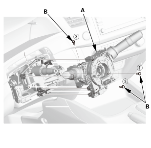
| 2. | Steering Column |
|
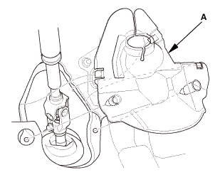
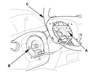
1. |
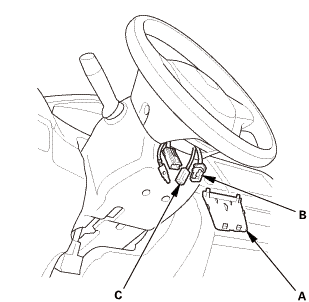
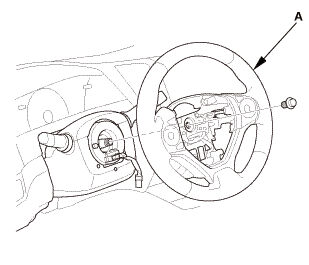
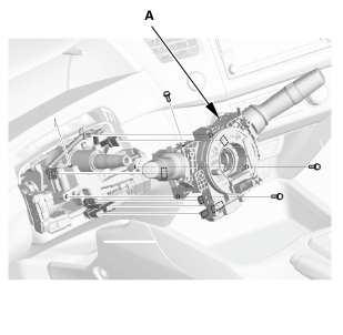
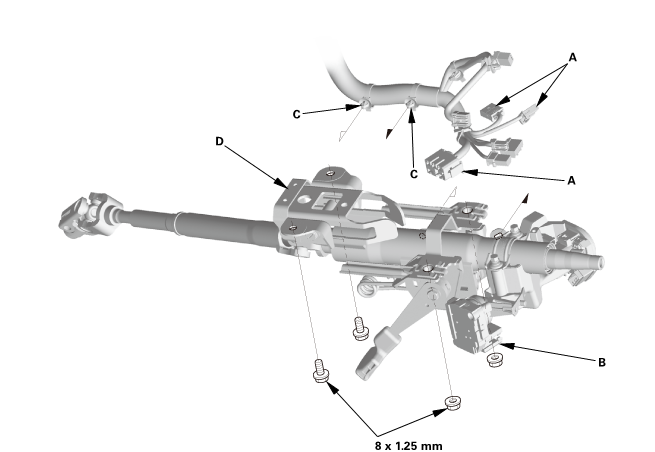
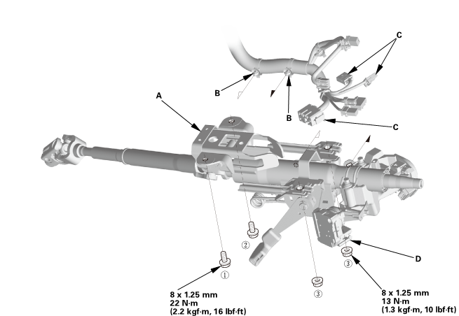
Install the steering column (A). |
|
|
NOTE: Do not release the lock lever until the steering column is installed. If the lock lever is released before installation, adjust the steering column after installation. |
||
Without steering lock
 22(22mm)
With steering lock
 u.
u.
|
2. |
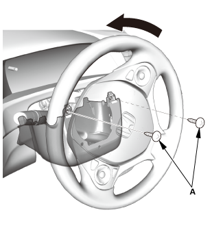
Loosely tighten the attaching nuts and bolts. |
|
3. |
Tighten the attaching nuts and bolts to the specified torque in the sequence shown. |
|
4. |
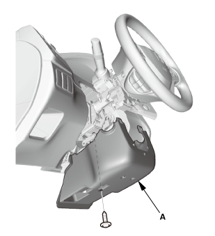
Install the wire harness clips (B) to the steering column. |
|
5. |
With steering lock: Connect the connectors (C) to the ignition switch (D). |
| 3. | Steering Column Lower Slide Shaft - Release |
|
|
|
| 4. | Steering Joint - Reconnection |
|
|
|
||||||||||||||||||||
|
|
|
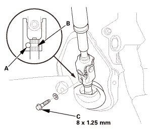
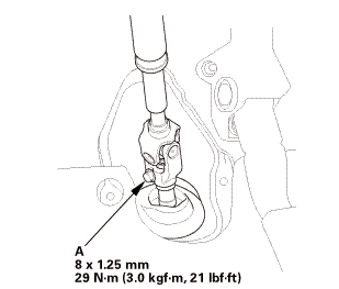
| 5. | Steering Joint Bolt - Tighten |
|
|
|
 mm:.o21
| 6. | Steering Joint Cover |
|
|
|
| 7. | Immobilizer-Keyless Control Unit |
|
|
|

| 8. | Combination Switch Body Assembly |
|
Without steering lock
With steering lock
|
|
|
|
|
|
|
|
| 9. | Lower Column Cover |
|
|
|
|
|
|
| 10. | Upper Column Cover |
|
|
|
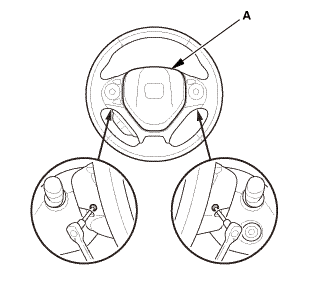
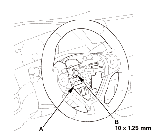
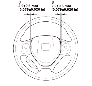
| 11. | Steering Wheel Assembly |
|
|
|
|
|
|
|||||||||
|
|
|
 no
no| 12. | Driver's Airbag |
|
|
|
||||||||||
 mmmmin)in!
|
|
|
||||||||||||

| 13. | Battery Terminal (SRS) - Reconnection |
|
|
|
|||||||||||||||||||
 (o.2ao.sam.
| 14. | Confirm Proper SRS Operation |
|
| 15. | Steering After Install - Check |
|
|||||||||||||||||||
| 16. | Front Toe - Inspection |
|
|||||||||||||||||||||||||
| 17. | HDS DLC - Connection |
|
|
|

| 18. | VSA Sensor Neutral Position - Memorization |
|
||||||||||
| 19. | Steering Angle Sensor Neutral Position - Clear |
|
|||||||
| 20. | Immobilizer Key - Registration |
|
| 21. | Keyless Access System - Registration |
|
 Ignition Switch Removal and Installation
725120
Removal
SRS components are located in this area. Review the SRS component locations
and the precautions and procedures before doing repairs or service.
1 ...
 Keyless Access LF Antenna (Rear Interior) Removal and Installation
1.
Rear Interior LF Antenna
1.
Open the trunk lid.
2. ...
See also:
Honda Civic Service Manual. Trunk Lid Outer Handle Switch Removal and Installation (2-door)
1.
Trunk Lid Trim Panel
1.
Remove the trunk lid trim panel (A).
2.
Trunk Lid Outer Handle Switch
...
