Honda Civic Service Manual: Steering Column Removal and Installation

|
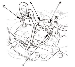
SRS components are located in this area. Review the SRS component locations, and the precautions and procedures before doing repairs or service. |
| 1. | Battery Terminal (SRS) - Disconnection |
|
|
|
||||||||||||||||||||||||||||||

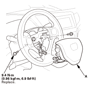
| 2. | Driver's Airbag |
|
|
|
|
|
|
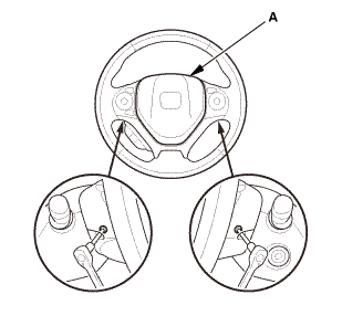
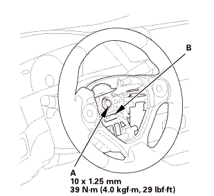
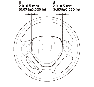
| 3. | Steering Wheel Assembly |
|
|
|
 wxusmm
|
|
|
||||||||||||||||||||
|
|
|
| 4. | Upper Column Cover |
|
|
|
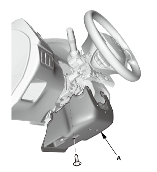
| 5. | Lower Column Cover |
|
|
|
|
|
|
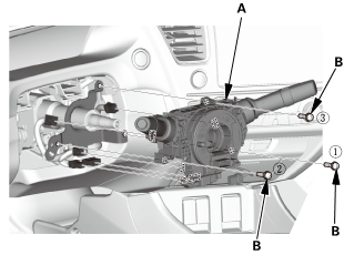
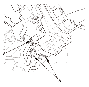
| 6. | Combination Switch Body Assembly |
|
|
|
|
|
|
|
Without steering lock
With steering lock
|
|
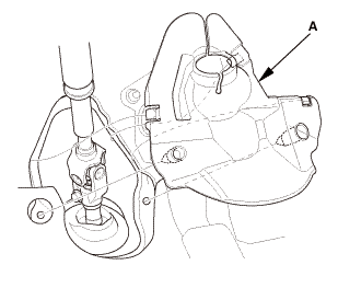
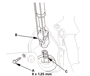
| 7. | Steering Joint Cover |
|
|
|
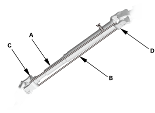
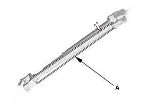
| 8. | Steering Column Lower Slide Shaft - Hold |
|
|
|
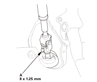
| 9. | Steering Joint Bolt - Loosen |
|
|
|
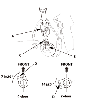
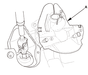
| 10. | Steering Joint - Disconnection |
|
|
|
||||||||||||||||||||
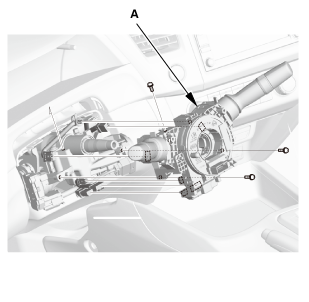
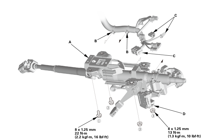
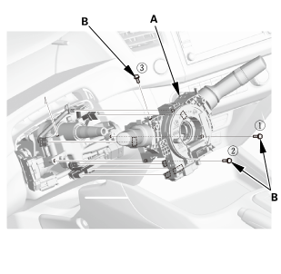
| 11. | Steering Column |
|
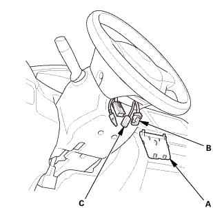
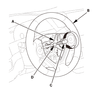
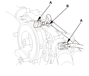
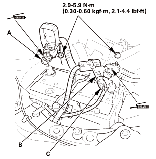
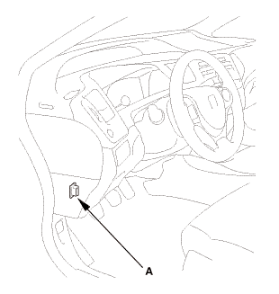
1. |
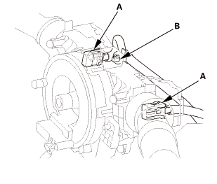
With steering lock: Disconnect the connectors (A) from the ignition switch (B). |
Without steering lock
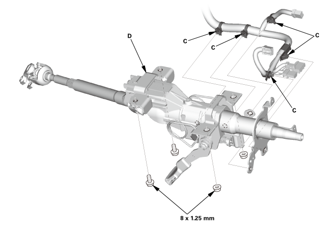
With steering lock
|
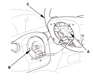
2. |
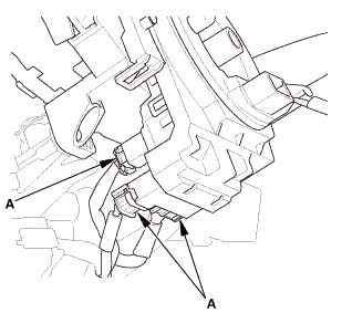
Detach the wire harness clips (C) from the steering column. |
|
3. |
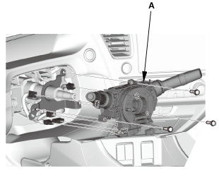
Remove the steering column (D). |
|
|
NOTE: Do not release the lock lever until the steering column is installed. If the lock lever is released before installation, adjust the steering column after installation. |
||

|
SRS components are located in this area. Review the SRS component locations, and the precautions and procedures before doing repairs or service. |
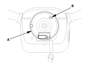
| 1. | Steering Column |
|
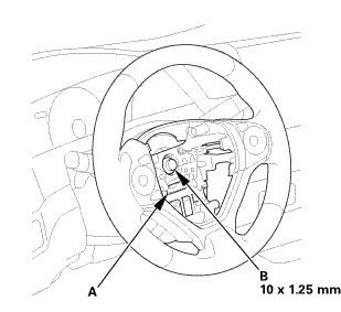
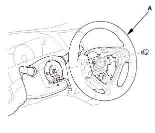
1. |
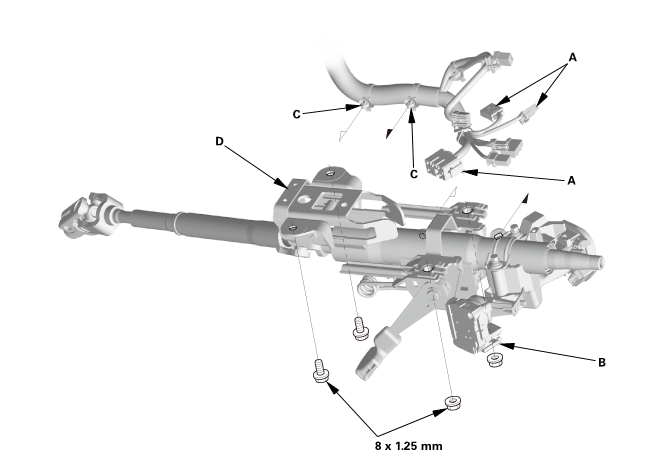
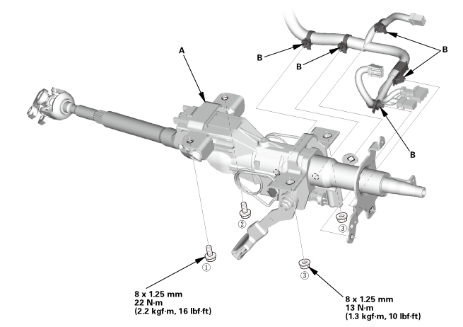
Install the steering column (A). |
|
|
NOTE: Do not release the lock lever until the steering column is installed. If the lock lever is released before installation, adjust the steering column after installation. |
||
Without steering lock
 22(22mm)
With steering lock
 u.
u.
|
2. |
Loosely tighten the attaching nuts and bolts. |
|
3. |
Tighten the attaching nuts and bolts to the specified torque in the sequence shown. |
|
4. |
Install the wire harness clips (B) to the steering column. |
|
5. |
With steering lock: Connect the connectors (C) to the ignition switch (D). |
| 2. | Steering Column Lower Slide Shaft - Release |
|
|
|
| 3. | Steering Joint - Reconnection |
|
|
|
||||||||||||||||||||
|
|
|
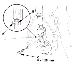
| 4. | Steering Joint Bolt - Tighten |
|
|
|
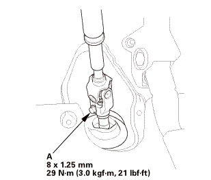 mm:.o21
| 5. | Steering Joint Cover |
|
|
|
| 6. | Combination Switch Body Assembly |
|
Without steering lock
With steering lock
|
|
|
|
|
|
|
|
| 7. | Lower Column Cover |
|
|
|
|
|
|
| 8. | Upper Column Cover |
|
|
|

| 9. | Steering Wheel Assembly |
|
|
|
|
|
|
|||||||||
|
|
|
 no
no| 10. | Driver's Airbag |
|
|
|
||||||||||
 mmmmin)in!
|
|
|
||||||||||||

| 11. | Battery Terminal (SRS) - Reconnection |
|
|
|
|||||||||||||||||||
 (o.2ao.sam.
| 12. | Confirm Proper SRS Operation |
|
| 13. | Steering After Install - Check |
|
|||||||||||||||||||
| 14. | Front Toe - Inspection |
|
|||||||||||||||||||||||||
| 15. | HDS DLC - Connection |
|
|
|
| 16. | VSA Sensor Neutral Position - Memorization |
|
||||||||||
| 17. | Steering Angle Sensor Neutral Position - Clear |
|
|||||||
 Steering Tie-Rod End Ball Joint Boot Replacement
5111A8 LEFT
5111A9 RIGHT
5111B0 BOTH
1.
Vehicle Lift
1.
Raise the vehicle on a lift, and make sure it is securely sup ...
 Steering Wheel Disassembly and Reassembly
Disassembly
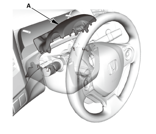
1.
HFL Switch
1.
Remove the lid (A).
2.
...
See also:
Honda Civic Owners Manual. Adjusting the Shoulder Anchor
The front seats have adjustable shoulder anchors to accommodate taller and
shorter
occupants.
1. Move the anchor up and down while
pulling the release outward.
2. Position the anchor so that the belt rests
across the center of your chest and over
your shoulder.
Adjusting the Shoulder ...
