Honda Civic Service Manual: Right Front Driveshaft Outboard Boot Replacement
219142 RIGHT
219140 BOTH

|
|
1.
|
Raise the vehicle on a lift, and make sure it is securely supported.
|
|
| 2. |
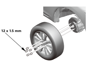
Tire and Wheel-Removal, Front Right |
|
 12x1mm 12x1mm
|
|
1.
|
Remove the right front wheel.
|
|
| 3. |
Driveshaft Spindle Nut, Front Right |
|
|
|
1.
|
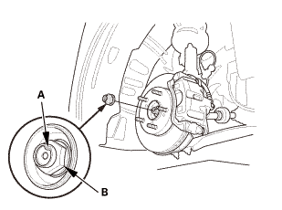
Pry up the stake (A) on the spindle nut (B).
|
|
2.
|
Remove the spindle nut.
|
|
|
|
|
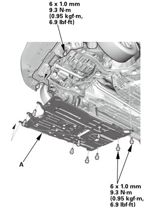
1.
|
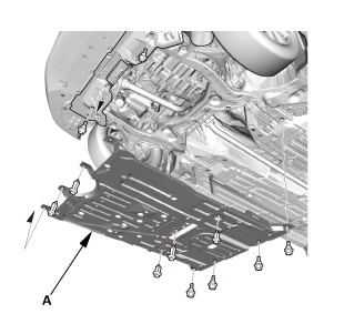
Remove the engine undercover (A).
|
|
| 5. |
MTF Replacement (M/T -Without Intermediate Shaft) |
|
|
|
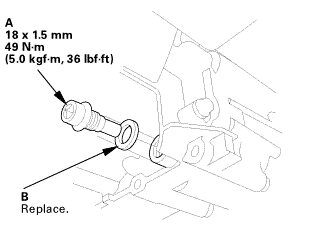
1.
|
Remove the drain plug (A) and the sealing washer (B), and drain
the MTF.
|
|
2.
|
Reinstall the drain plug with a new sealing washer.
|
|
| 6. |
ATF Replacement (A/T -Without Intermediate Shaft) |
|
|
|
1.
|
Remove the drain plug (A), and drain the ATF.
|
|
2.
|
Reinstall the drain plug using a new sealing washer (B).
|
|
| 7. |
Right Lower Ball Joint Lower Arm Side Disconnection |
|
|
|
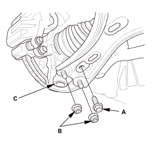
1.
|
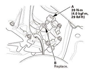
Remove the flange bolt (A).
|
|
2.
|
Remove the flange nuts (B).
|
|
3.
|
Disconnect the lower ball joint (C) from the lower arm.
|
|
| 8. |
Driveshaft Front Right - Disconnection, Outboard Side |
|
|
|
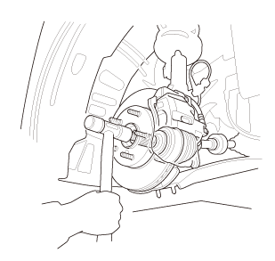
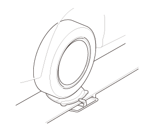
1.
|
Separate the outboard joint from the front hub using a soft face
hammer.
|
|
|
|
|
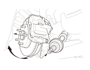
2.
|
Pull the knuckle outward, and separate the outboard joint from
the front hub.
|
|
| 9. |
Right Front Driveshaft Inboard Side - Disconnection (With Intermediate
Shaft) |
|
|
|
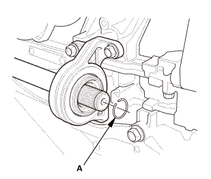
1.
|
Drive the inboard joint (A) off of the intermediate shaft using
a drift punch and a hammer.
|
|
NOTE: Do not pull on the driveshaft or the inboard joint may
come apart.
|
|
|
|
|
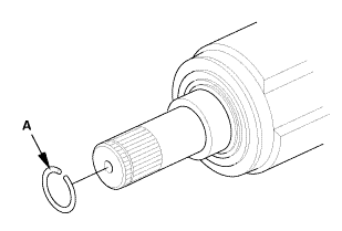
2.
|
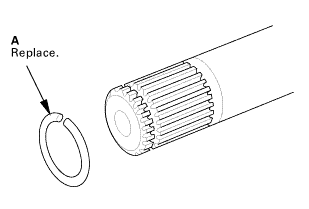
Remove the set ring (A).
|
|
| 10. |
Right Front Driveshaft Inboard Side - Disconnection (Without Intermediate
Shaft) |
|
|
|
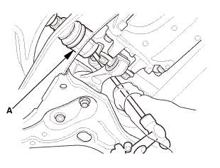
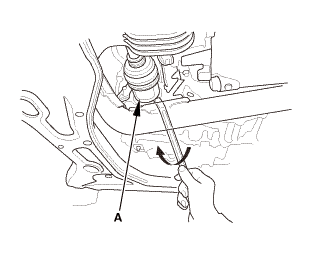
1.
|
Pry the inboard joint (A) from the differential using a pry bar.
|
|
NOTE:
|
|

|
Do not pull on the driveshaft or the inboard
joint may come apart. Pull the inboard joint straight
out to avoid damaging the oil seal.
|
|
|
|
Be careful not to damage the oil seal or the
end of the inboard using the pry bar.
|
|
|
|
|
|
|
2.
|
Remove the set ring (A).
|
|
| 11. |
Front Outboard Joint, Right |
|
|
|
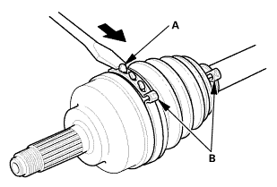
1.
|
Lift up the three tabs (A) using a flat-tipped screwdriver.
|
|
NOTE: Be careful not to damage the boot.
|
|
2.
|
Release the ear clamp bands (B).
|
|
|
|
|
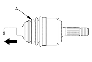
3.
|
Slide the outboard boot (A) partially toward the inboard joint
side.
|
|
NOTE: Be careful not to damage the boot.
|
|
|
|
|
4.
|
Wipe off the grease to expose the driveshaft and the outboard
joint inner race.
|
|
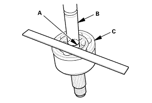
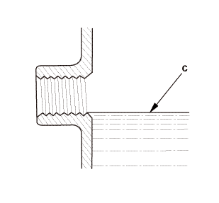
5.
|
Make a mark (A) on the driveshaft (B) at the same level as the
outboard joint end (C).
|
|
|
 22mmmmn7xacnnmna 22mmmmn7xacnnmna
|
|
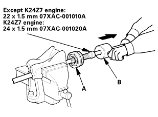
6.
|
Securely clamp the driveshaft in a bench vise with a shop towel
wrapped around the driveshaft.
|
|
7.
|
Remove the outboard joint (A) using the threaded adapter and
a commercially available 5/8’’-18 UNF slide hammer (B).
|
|
8.
|
Remove the driveshaft from the bench vise.
|
|
|
|
|
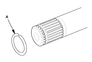
9.
|
Remove the stop ring (A).
|
|
| 12. |
Front Outboard Boot, Right |
|
|
|
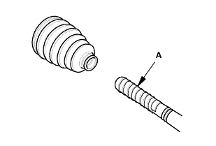
1.
|
Wrap the splines on the driveshaft with vinyl tape (A) to prevent
damaging the outboard boot.
|
|
2.
|
Remove the outboard boot.
|
|
NOTE: Be careful not to damage the boot.
|
|

|
NOTE: Refer to the Exploded View in the Front Driveshaft Disassembly
and Reassembly, as needed, during this procedure.
|
| 1. |
Front Outboard Boot, Right |
|
|
|
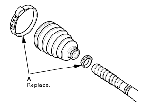
1.
|
Install new ear clamp bands (A) and the outboard boot onto the
driveshaft.
|
|
NOTE: Be careful not to damage the boot.
|
|
2.
|
Remove the vinyl tape.
|
|
| 2. |
Front Outboard Joint, Right |
|
|
|
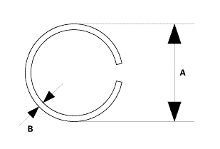
1.
|
Make sure to check the size of a new stop ring.
|
|

To avoid driveshaft and vehicle damage, make sure you install
a new stop ring.
|
|
Stop ring specifications
|
Model
|
Factory
|
Overall diameter (A)
|
Wire diameter (B)
|
|
M/T (Except K24Z7 engine)
|
Japan-produced
|
26.0 mm
(1.024 in)
|
2.0 mm
(0.079 in)
|
|
25.1 mm
(0.988 in)
|
2.0 mm
(0.079 in)
|
|
North America-produced
|
24.3 mm
(0.957 in)
|
1.6 mm
(0.063 in)
|
|
M/T (K24Z7 engine)
|
|
29.8 mm
(1.173 in)
|
1.8 mm
(0.071 in)
|
|
A/T
|
Japan-produced
|
23.5 mm
(0.925 in)
|
2.0 mm
(0.079 in)
|
|
North America-produced
|
22.2 mm
(0.874 in)
|
1.6 mm
(0.063 in)
|
|
|
|
|
|
|
|
2.
|
Install the stop ring (A).
|
|
|
 usemehum usemehum
|
|
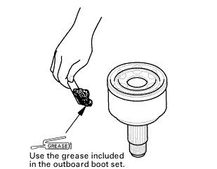
3.
|
Pack about 35 g (1.23 oz) of grease included in the new outboard
boot set into the driveshaft hole in the outboard joint.
|
|
NOTE: If you are installing a new outboard joint, the grease
is already installed.
|
|
|
|
|
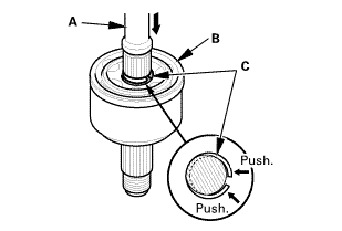
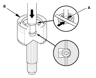
4.
|
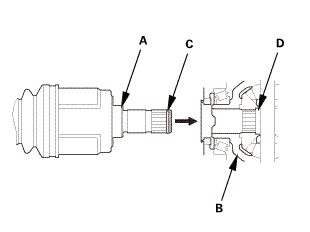
Insert the driveshaft (A) into the outboard joint (B) until the
stop ring (C) is close to the joint.
|
|
|
|
|
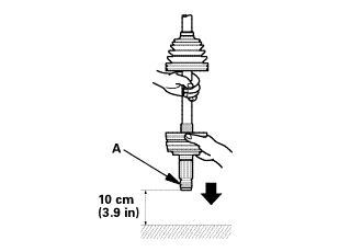
5.
|
To completely seat the outboard joint, pick up the driveshaft
and the joint, and tap or hit the assembly onto a hard surface from
a height of about 10 cm (3.9 in).
|
|
NOTE: Do not use a hammer, as excessive force may damage the
driveshaft. Be careful not to damage the threaded section (A) of
the outboard joint.
|
|
|
|
|
6.
|
Check the alignment of the paint mark (A) you made with the outboard
joint end (B).
|
|
To avoid driveshaft and vehicle damage, the shaft must be all
the way into the outboard joint to ensure the stop ring is properly
seated.
|
|
|
|
|
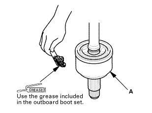
7.
|
Pack the outboard joint (A) with the remaining joint grease included
in the outboard boot set.
|
|
Total grease quantity Outboard joint:
|
Model
|
Factory
|
Quantity
|
|
M/T (Except K24Z7 engine)
|
Japan-produced
|
85-95 g
(3.00-3.35 oz)
|
|
North America-produced
|
120-140 g
(4.23-4.94 oz)
|
|
M/T (K24Z7 engine)
|
|
110-130 g
(3.88-4.59 oz)
|
|
A/T
|
Japan-produced
|
95-105 g
(3.35-3.70 oz)
|
|
North America-produced
|
85-105 g
(3.00-3.70 oz)
|
|
|
|
|
|
|
|
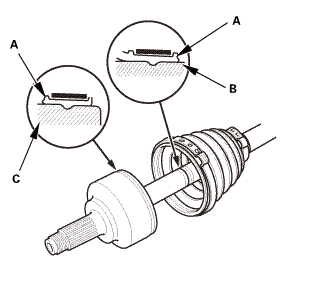
8.
|
Fit the boot ends (A) onto the driveshaft (B) and the outboard
joint (C).
|
|
9.
|
Bleed any excess air from the boot by inserting a flat-tipped
screwdriver between the boot and the joint.
|
|
|
M/T
A/T
|
|
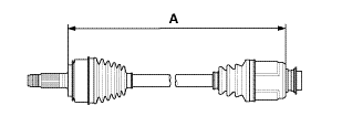
10.
|
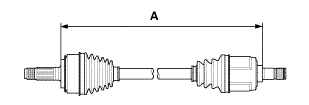
Inspect the length (A) of the driveshafts in the figure as shown,
then adjust the boots to halfway between full compression and full
extension.
|
|
Driveshaft length
|
Model
|
Factory
|
Specified length (A)
|
|
M/T (Except K24Z7 engine)
|
Japan-produced
|
487-492 mm
(19.17-19.37 in)
|
|
North America-produced
|
493-498 mm
(19.41-19.61 in)
|
|
M/T (K24Z7 engine)
|
|
429.65-434.65 mm
(16.9153-17.1122 in)
|
|
A/T
|
Japan-produced
|
804-809 mm
(31.65-31.85 in)
|
|
North America-produced
|
802.3-807.3 mm
(31.587-31.783 in)
|
|
|
|
|
|
|
|
11.
|
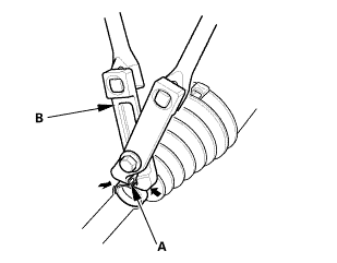
Close the ear portion (A) of the band using a commercially available
boot band clamp tool (Kent-Moore J-35910 or equivalent) (B).
|
|
|
 mmmax15mmmaxrun:[0maxnam:mm[0onmax mmmax15mmmaxrun:[0maxnam:mm[0onmax
|
|
12.
|
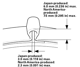
Check the clearance between the closed ear portion of the band.
If the clearance is not within the standard, close the ear portion
of the band tighter.
|
|
| 3. |
Right Front Driveshaft Inboard Side - Reconnection (Without Intermediate
Shaft) |
|
|
|
1.
|
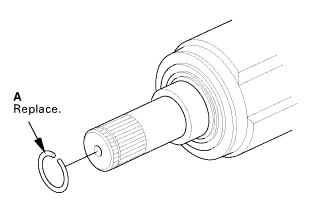
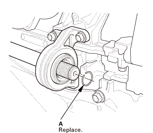
Install a new set ring (A).
|
|
|
|
|
2.
|
Clean the areas where the driveshaft contacts the differential
thoroughly with solvent.
|
|
NOTE: Do not wash the rubber parts with solvent.
|
|
3.
|
Dry the areas where the driveshaft contacts the differential
thoroughly with compressed air.
|
|
4.
|
Insert the inboard end (A) of the driveshaft into the differential
(B) until the set ring (C) locks in the groove (D).
|
|
NOTE: Insert the driveshaft horizontally to prevent damaging
the oil seal.
|
|
| 4. |
Right Front Driveshaft Inboard Side - Reconnection (With Intermediate
Shaft) |
|
|
|
1.
|
Install a new set ring (A).
|
|
|
 (p/n (p/n
|
|
2.
|
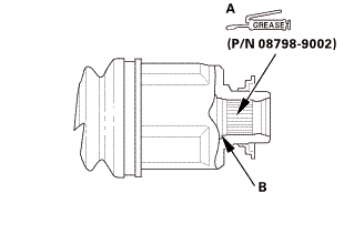
Apply 0.5-1.0 g (0.018-0.035 oz) of super high temp urea
grease (P/N 08798-9002) to the whole splined surface (A) of the
right driveshaft.
|
|
3.
|
After applying grease, remove the grease from the splined grooves
at intervals of 2-3 splines and from the set ring groove (B) so
that air can bleed from the intermediate shaft.
|
|
|
 ei ei
|
|
4.
|
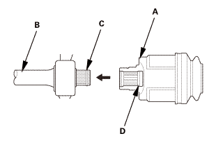
Insert the inboard end (A) of the driveshaft onto the intermediate
shaft (B) until the set ring (C) locks in the groove (D).
|
|
| 5. |
Driveshaft Front Right - Reconnection, Outboard Side |
|
|
|
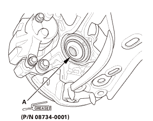
1.
|
Apply about 5 g (0.18 oz) of moly 60 paste (P/N 08734-0001) to
the contact area (A) of the outboard joint and the front wheel bearing.
|
|
NOTE: The paste helps to prevent noise and vibration.
|
|
|

|
|
2.
|
Install the outboard joint (A) into the front hub (B) on the
knuckle.
|
|
| 6. |
Right Lower Ball Joint Lower Arm Side Reconnection |
|
 replace. replace.
|
|
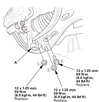
1.
|
Connect the lower ball joint (A) to the lower arm.
|
|
2.
|
Install new flange nuts and a new flange bolt in the sequence
shown.
|
|
| 7. |
Driveshaft Spindle Nut, Front Right |
|
 22mmmmengine:mmn-m 22mmmmengine:mmn-m
|
|
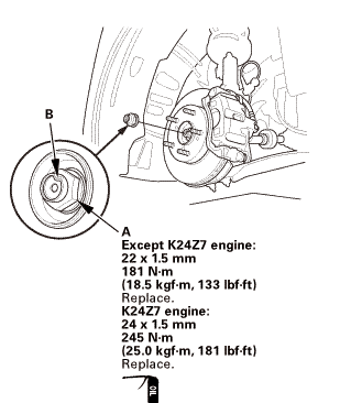
1.
|
Apply a small amount of engine oil to the seating surface of
a new spindle nut (A).
|
|
2.
|
Install the spindle nut.
|
|
3.
|
Use a drift to stake the spindle nut shoulder (B) against the
driveshaft.
|
|
| 8. |
Tire and Wheel-Installation, Front Right |
|
 mminmuan mminmuan
|
|
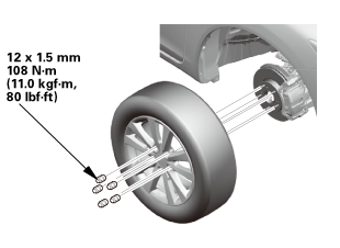
1.
|
Install the right front wheel.
|
|
NOTE: Before installing the wheel, clean the mating surfaces
between the brake disc and the inside of the wheel.
|
|
| 9. |
Driveshaft After Install Check |
|
|
1.
|
Turn the wheel by hand, and make sure there is no interference
between the driveshaft and surrounding parts.
|
|
| 10. |
ATF Replacement (A/T -Without Intermediate Shaft) |
|
|
|
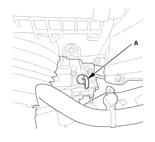
1.
|
Remove the ATF dipstick (yellow loop) (A), and wipe it with a
clean cloth.
|
|
|
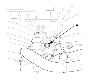
2.
|
Refill the transmission with the recommended fluid through the dipstick
hole (A) to bring the fluid level between the upper mark and the lower mark
of the dipstick. Always use Honda automatic transmission fluid (ATF) ATF
DW-1. Using a non-Honda ATF can affect shift quality.
|
|
Automatic Transmission Fluid Capacity:
| |
2.4 L (2.5 US qt) at change
|
| |
5.75 L (6.08 US qt) at overhaul
|
|
|
|
|
|
|
3.
|
Insert the ATF dipstick (A) back into the dipstick hole.
|
|
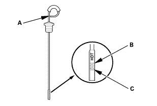
5.
|
Make sure the fluid level is between the upper mark (B) and the
lower mark (C) on the dipstick.
|
|
6.
|
Insert the dipstick back into the dipstick hole.
|
|
| 11. |
MTF Replacement (M/T -Without Intermediate Shaft) |
|
|
|
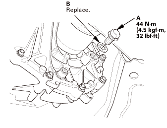
1.
|
Remove the filler plug (A) and the sealing washer (B).
|
|
2.
|
Refill the transmission with MTF to the proper level (C). Always
use Honda Manual Transmission Fluid (MTF).
|
|
Manual Transmission Fluid Capacity
|
Except K24Z7 engine:
|
| |
1.4 L (1.5 US qt) at fluid change
|
| |
1.6 L (1.7 US qt) at overhaul
|
|
K24Z7 engine:
|
| |
1.9 L (2.0 US qt) at fluid change
|
| |
2.0 L (2.1 US qt) at overhaul
|
|
|
|
|
3.
|
Reinstall the filler plug with a new sealing washer.
|
|
|
|
|
1.
|
Install the engine undercover (A).
|
|
|
|
For proper inspection and adjustment of the wheel alignment,
do these checks:
|
|
1.
|
Release the parking brake to avoid an incorrect measurement.
|
|
2.
|
Make sure the suspension is not modified.
|
|
3.
|
Make sure the fuel tank is full, and that the tire repair kit,
the spare tire, the jack, and the tools are in place on the vehicle.
|
|
4.
|
Check the tire size and tire pressure according to tire information.
|
|
|
|
Use commercially available computerized four wheel alignment
equipment to measure wheel alignment (caster, camber, toe, and turning
angle). Follow the equipment manufacturer's instructions.
|
|
1.
|
Check the caster angle.
|
|
USA and Canada models
|
Caster angle:
|
| |
Except Si:
|
5 ° 19 ’±30 ’
|
| |
Si (Without 18 inch wheel):
|
5 ° 22 ’±30 ’
|
| |
Si (With 18 inch wheel):
|
5 ° 15 ’±30 ’
|
|
|
|
|
Mexico models
|
Caster angle:
|
| |
Without 18 inch wheel:
|
5 ° 10 ’±30 ’
|
| |
With 18 inch wheel:
|
5 ° 6 ’±30 ’
|
|
|
|
|
|
If the measurement is within specifications,
measure the front camber angle.
|
|
|
|
If the measurement is not within specifications,
check for bent or damaged suspension components.
|
|
|
|
|
|
Use commercially available computerized four wheel alignment
equipment to measure wheel alignment (caster, camber, toe, and turning
angle). Follow the equipment manufacturer's instructions.
|
|
1.
|
Check the camber angle.
|
|
USA and Canada models
|
Camber angle:
|
| |
Except Si:
|
| |
|
Front:
|
0 ° 00 ’±30 ’
|
| |
|
Rear:
|
-0 ° 45 ’±45 ’
|
| |
Si (Without 18 inch wheel):
|
| |
|
Front:
|
-0 ° 04 ’±30 ’
|
| |
|
Rear:
|
-0 ° 52 ’±45 ’
|
| |
Si (With 18 inch wheel):
|
| |
|
Front:
|
-0 ° 18 ’±30 ’
|
| |
|
Rear:
|
-0 ° 45 ’±45 ’
|
|
(Maximum difference between the front right and
left side: 0 ° 45 ’)
|
|
|
|
|
Mexico models
|
Camber angle:
|
| |
Front:
|
0 ° 20 ’±30 ’
|
| |
Rear:
|
-0 ° 22 ’±45 ’
|
|
(Maximum difference between the front right and
left side: 0 ° 45 ’)
|
|
|
|
|
|
If the measurement is within specification, measure
the toe-in.
|
|
|
|
If the measurement for the front camber is not
within the specification, go to front camber adjustment.
|
|
|
|
If the measurement for the rear camber is not
within the specification, check for bent or damaged
suspension components.
|
|
|
|
| 16. |
Front Toe - Inspection |
|
|
Use commercially available computerized four wheel alignment
equipment to measure wheel alignment (caster, camber, toe, and turning
angle). Follow the equipment manufacturer's instructions.
|
|
1.
|
Set the steering column to the middle tilt position and telescopic
positions.
|
|
2.
|
Center the steering wheel spokes, and install a steering wheel
holder tool.
|
|
3.
|
Check the toe with the wheels pointed straight ahead.
|
|
Front toe-in: 0±2 mm (0±0.08 in)
|
|
|
If adjustment is required, go to the front toe
adjustment.
|
|
|
|
If no adjustment is required, remove the alignment
equipment.
|
|
|
|
| 17. |
Turning Angle - Inspection |
|
|
|
Use commercially available computerized four wheel alignment
equipment to measure wheel alignment (caster, camber, toe, and turning
angle). Follow the equipment manufacturer's instructions.
|
|
1.
|
Turn the wheel right and left while applying the brake, and measure
the turning angle of both wheels.
|
|
USA and Canada models
|
Turning angle:
|
| |
Except Si:
|
| |
|
Inward:
|
38 ° 30 ’±2 °
|
| |
|
Outward (reference):
|
30 ° 47 ’±1 °
|
| |
Si (Without 18 inch wheel):
|
| |
|
Inward:
|
38 ° 22 ’±2 °
|
| |
|
Outward (reference):
|
30 ° 41 ’±1 °
|
| |
Si (With 18 inch wheel):
|
| |
|
Inward:
|
36 ° 33 ’±2 °
|
| |
|
Outward (reference):
|
29 ° 53 ’±1 °
|
|
|
|
|
Mexico models
|
Turning angle:
|
| |
Without 18 inch wheel:
|
| |
|
Inward:
|
39 ° 12 ’±2 °
|
| |
|
Outward (reference):
|
31 ° 14 ’±1 °
|
| |
With 18 inch wheel:
|
| |
|
Inward:
|
36 ° 58 ’±2 °
|
| |
|
Outward (reference):
|
30 ° 16 ’±1 °
|
|
|
|
|
2.
|
If the measurement is not within the specifications, even up
both sides of the tie-rod threaded section length while adjusting
the front toe.
|
|
3.
|
If it is correct, but the turning angle is not within the specifications,
check for bent or damaged suspension components.
|
|
|
|
|
1.
|
Turn the wheel right and left while applying the brake, and measure
the turning angle of both wheels.
|
|
USA and Canada models
|
Turning angle:
|
| |
Except Si:
|
| |
|
Inward:
|
38 ° 43 ’±2 °
|
| |
|
Outward (reference):
|
30 ° 55 ’±1 °
|
| |
Si:
|
| |
|
Inward:
|
38 ° 36 ’±2 °
|
| |
|
Outward (reference):
|
30 ° 49 ’±1 °
|
|
|
|
|
Mexico models
|
Turning angle:
|
| |
Inward:
|
39 ° 15 ’±2 °
|
| |
Outward (reference):
|
31 ° 21 ’±1 °
|
|
|
|
|
2.
|
If the measurement is not within the specifications, even up
both sides of the tie-rod threaded section length while adjusting
the front toe.
|
|
3.
|
If it is correct, but the turning angle is not within the specifications,
check for bent or damaged suspension components.
|
|
|
|
1.
|
Test-drive the vehicle.
|
|
| 19. |
Maintenance Minder Reset (Without Intermediate Shaft) |
|
|
1.
|
After doing all procedures, select the individual maintenance
item you wish to reset with the HDS..
|
|
2191D2 RIGHT
2191D3 BOTH
1.
Vehicle Lift
1.
Raise the vehicle on a lift, and make sure it is securely supported.
...
219132 RIGHT FRONT
219130 BOTH FRONT
1.
Vehicle Lift
1.
Raise the vehicle on a lift, and make sure it is securely suppor ...
See also:
Honda Civic Owners Manual. Checking and Maintaining Wiper Blades
Checking Wiper Blades
If the wiper blade rubber has deteriorated, it will leave streaks and the
hard surfaces
of the blade may scratch the window glass.
Changing the Wiper Blade Rubber
Turn the ignition switch to LOCK 0*1.
While holding the wiper switch in the MIST
position, t ...
 Right Front Driveshaft Inboard Boot Replacement
 Right Front Driveshaft Removal and Installation