Honda Civic Service Manual: Right Front Driveshaft Inboard Boot Replacement
2191D2 RIGHT
2191D3 BOTH

| 1. | Vehicle Lift |
|
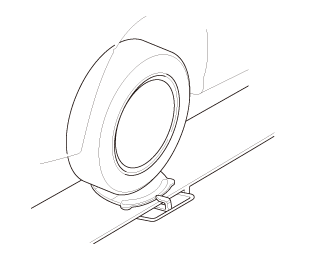
| 2. | Tire and Wheel-Removal, Front Right |
|
|
|
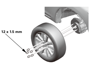 12x1mm
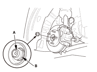
| 3. | Driveshaft Spindle Nut, Front Right |
|
|
|
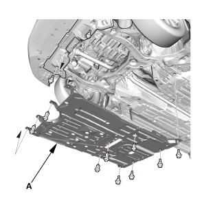
| 4. | Engine Undercover |
|
|
|
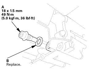
| 5. | MTF Replacement (M/T -Without Intermediate Shaft) |
|
|
|
| 6. | ATF Replacement (A/T -Without Intermediate Shaft) |
|
|
|
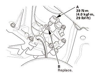
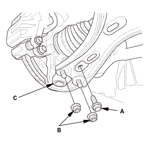
| 7. | Right Lower Ball Joint Lower Arm Side Disconnection |
|
|
|
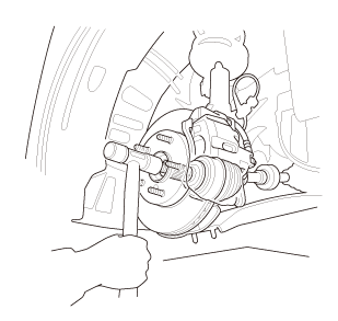
| 8. | Driveshaft Front Right - Disconnection, Outboard Side |
|
|
|
|
|
|
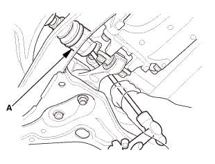
| 9. | Right Front Driveshaft Inboard Side - Disconnection (With Intermediate Shaft) |
|
|
|
||||||
|
|
|
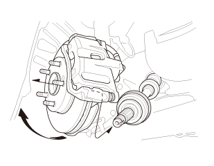
| 10. | Right Front Driveshaft Inboard Side - Disconnection (Without Intermediate Shaft) |
|
|
|
|||||||||||||||||

|
|
|
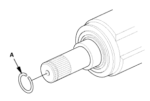
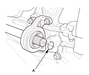
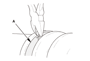
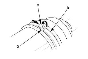
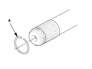
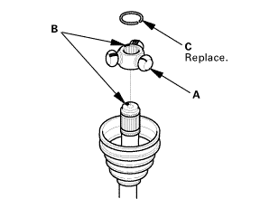
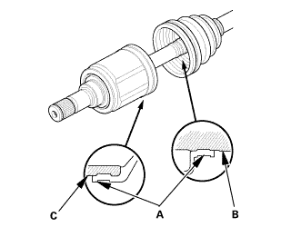
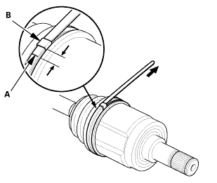
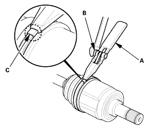
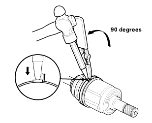
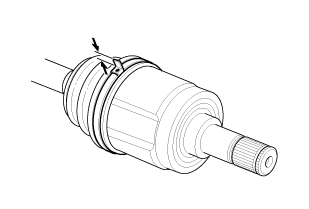
| 11. | Front Inboard Joint, Right |
|
Welded type
Double loop type
Low profile type
Ear clamp type
|
|
|||||||||||||||||||||||||
|
|
|
||||||||||||
|
|
|
||||||||||||
|
|
|
|
|
|
|||||||||
|
|
|
|
|
|
|||||||||||||||||||||

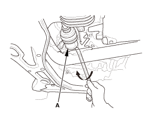
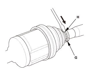
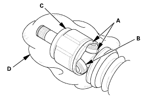
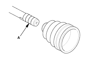
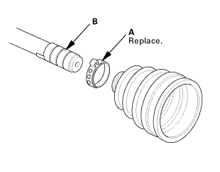
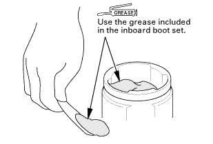
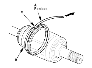
| 12. | Front Inboard Boot, Right |
|
|
|
|||||||||

|
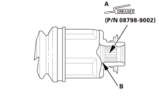
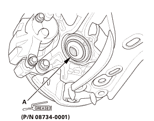
NOTE: Refer to the Exploded View in the Front Driveshaft Disassembly and Reassembly, as needed, during this procedure. |
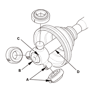
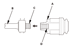
| 1. | Front Inboard Boot, Right |
|
|
|
||||||||||||
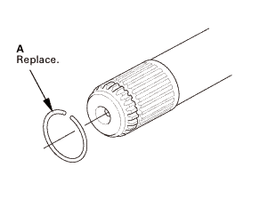
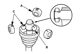
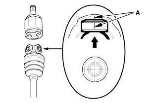
| 2. | Front Inboard Joint, Right |
|
|
|
|
|
|
||||||
|
|
|
|
|
|
|
|
|
||||||

|
|
|
|
|
|
||||||||||||||
|
|
|
||||||||||||||||||||||||
 ininbaardhaul
|
|
|
||||||||||||||
|
|
|
|
M/T
A/T
|
|
||||||||||||||||||||||||
|
|
|
|||||||||||||||||||||||||||
|
|
|
|
|
|
|
|
|
|
|
|
|
|
|
|||||||||||||||||
|
|
|
|
|
|
|
|
|
|
|
|
 1nmm(nmax21
| 3. | Right Front Driveshaft Inboard Side - Reconnection (Without Intermediate Shaft) |
|
|
|
|
|
|
|||||||||||||||
| 4. | Right Front Driveshaft Inboard Side - Reconnection (With Intermediate Shaft) |
|
|
|
|
|
|
 (p/n
(p/n|
|
|
 ei
ei| 5. | Driveshaft Front Right - Reconnection, Outboard Side |
|
|
|
||||||
|
|
|

| 6. | Right Lower Ball Joint Lower Arm Side Reconnection |
|
|
|
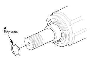
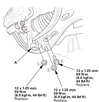 replace.
| 7. | Driveshaft Spindle Nut, Front Right |
|
|
|
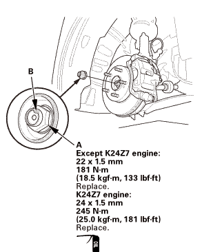 22mmmmengine:mmn-m
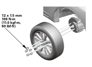
| 8. | Tire and Wheel-Installation, Front Right |
|
|
|
||||||
 mminmuan
| 9. | Driveshaft After Install Check |
|
| 10. | ATF Replacement (A/T -Without Intermediate Shaft) |
|
|
|
|
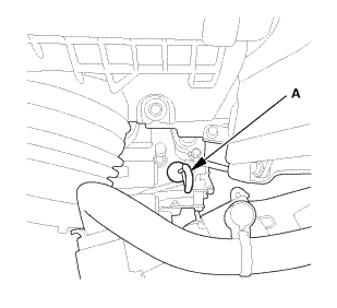
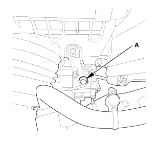
2. |
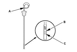
Refill the transmission with the recommended fluid through the dipstick hole (A) to bring the fluid level between the upper mark and the lower mark of the dipstick. Always use Honda automatic transmission fluid (ATF) ATF DW-1. Using a non-Honda ATF can affect shift quality. |
|||||||
|
Automatic Transmission Fluid Capacity:
|
||||||||
|
|
|
| 11. | MTF Replacement (M/T -Without Intermediate Shaft) |
|
|
|
||||||||||||||||||||||||||
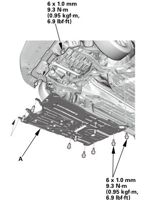
| 12. | Engine Undercover |
|
|
|
| 13. | Pre-Alignment Checks |
|
| 14. | Caster - Inspection |
|
|||||||||||||||||||||||||||||||||||||||||||||||
| 15. | Camber - Inspection |
|
||||||||||||||||||||||||||||||||||||||||||||||||||||||||||||||||||||||||||||||||||||||
| 16. | Front Toe - Inspection |
|
|||||||||||||||||||||||||
| 17. | Turning Angle - Inspection |
|
|
|
|||||||||||||||||||||||||||||||||||||||||||||||||||||||||||||||||||||||||||||||||||||||||
|
|
|
|||||||||||||||||||||||||||||||||||||||||||||||||||||||||
| 18. | Test Drive |
|
| 19. | Maintenance Minder Reset (Without Intermediate Shaft) |
|
 Right Front Driveshaft Dynamic Damper Removal and Installation
1.
Vehicle Lift
1.
Raise the vehicle on a lift, and make sure it is securely supported.
2. ...
 Right Front Driveshaft Outboard Boot Replacement
219142 RIGHT
219140 BOTH
1.
Vehicle Lift
1.
Raise the vehicle on a lift, and make sure it is securely supported.
...
See also:
Honda Civic Service Manual. Rear Seat-Back Cover Removal and Installation (Natural Gas models)
Removal
1.
Rear Seat Cushion
1.
Remove the bolt (A) securing the rear seat cushion (B).
2.
While ...
