Honda Civic Service Manual: Right Front Driveshaft Removal and Installation
219132 RIGHT FRONT
219130 BOTH FRONT

| 1. | Vehicle Lift |
|
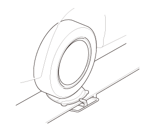
| 2. | Tire and Wheel-Removal, Front Right |
|
|
|
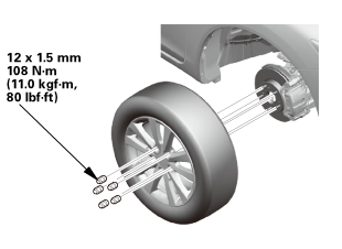
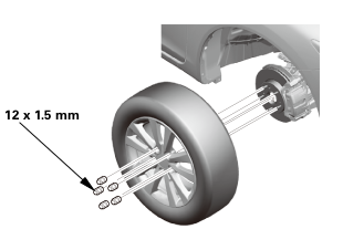 12x1mm
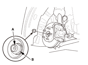
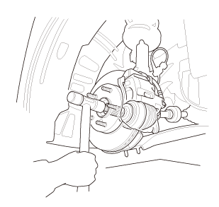
| 3. | Driveshaft Spindle Nut, Front Right |
|
|
|
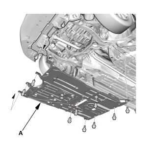
| 4. | Engine Undercover |
|
|
|
| 5. | MTF Replacement (M/T -Without Intermediate Shaft) |
|
|
|
| 6. | ATF Replacement (A/T -Without Intermediate Shaft) |
|
|
|
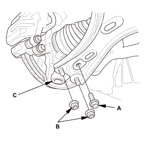
| 7. | Right Lower Ball Joint Lower Arm Side Disconnection |
|
|
|
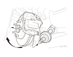
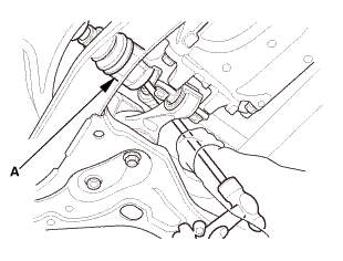
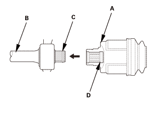
| 8. | Driveshaft Front Right - Disconnection, Outboard Side |
|
|
|
|
|
|
| 9. | Right Front Driveshaft Inboard Side - Disconnection (With Intermediate Shaft) |
|
|
|
||||||
|
|
|
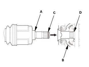
| 10. | Right Front Driveshaft Inboard Side - Disconnection (Without Intermediate Shaft) |
|
|
|
|||||||||||||||||

|
|
|

| 1. | Right Front Driveshaft Inboard Side - Reconnection (Without Intermediate Shaft) |
|
|
|
|
|
|
|||||||||||||||
| 2. | Right Front Driveshaft Inboard Side - Reconnection (With Intermediate Shaft) |
|
|
|
|
|
|
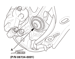
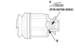 (p/n
(p/n|
|
|
 ei
ei| 3. | Driveshaft Front Right - Reconnection, Outboard Side |
|
|
|
||||||
|
|
|

| 4. | Right Lower Ball Joint Lower Arm Side Reconnection |
|
|
|
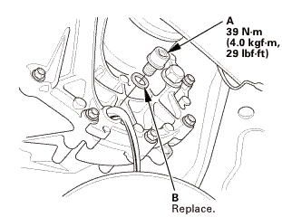
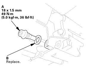
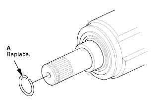
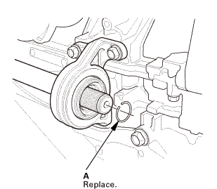
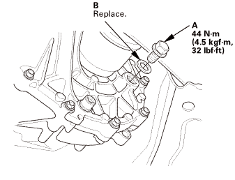
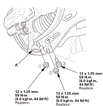 replace.
| 5. | Driveshaft Spindle Nut, Front Right |
|
|
|
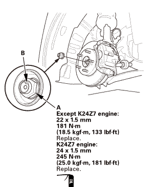 22mmmmengine:mmn-m
| 6. | Tire and Wheel-Installation, Front Right |
|
|
|
||||||
 mminmuan
| 7. | Driveshaft After Install Check |
|
| 8. | ATF Replacement (A/T -Without Intermediate Shaft) |
|
|
|
|
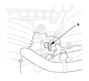
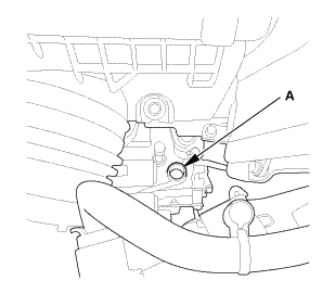
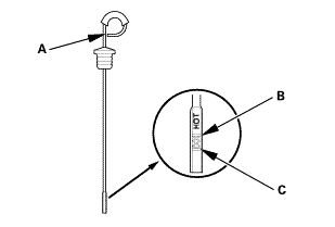
2. |
Refill the transmission with the recommended fluid through the dipstick hole (A) to bring the fluid level between the upper mark and the lower mark of the dipstick. Always use Honda automatic transmission fluid (ATF) ATF DW-1. Using a non-Honda ATF can affect shift quality. |
|||||||
|
Automatic Transmission Fluid Capacity:
|
||||||||
|
|
|
| 9. | MTF Replacement (M/T -Without Intermediate Shaft) |
|
|
|
||||||||||||||||||||||||||
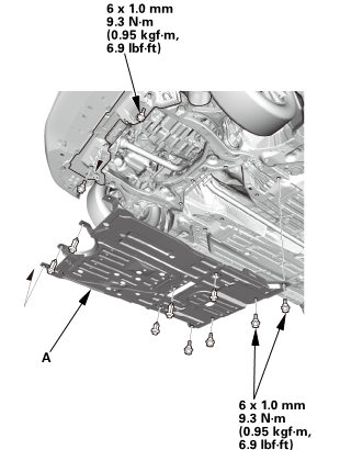
| 10. | Engine Undercover |
|
|
|
| 11. | Pre-Alignment Checks |
|
| 12. | Caster - Inspection |
|
|||||||||||||||||||||||||||||||||||||||||||||||
| 13. | Camber - Inspection |
|
||||||||||||||||||||||||||||||||||||||||||||||||||||||||||||||||||||||||||||||||||||||
| 14. | Front Toe - Inspection |
|
|||||||||||||||||||||||||
| 15. | Turning Angle - Inspection |
|
|
|
|||||||||||||||||||||||||||||||||||||||||||||||||||||||||||||||||||||||||||||||||||||||||
|
|
|
|||||||||||||||||||||||||||||||||||||||||||||||||||||||||
| 16. | Test Drive |
|
| 17. | Maintenance Minder Reset (Without Intermediate Shaft) |
|
 Right Front Driveshaft Outboard Boot Replacement
219142 RIGHT
219140 BOTH
1.
Vehicle Lift
1.
Raise the vehicle on a lift, and make sure it is securely supported.
...
 Engine
...
See also:
Honda Civic Owners Manual. Maintain a Proper Sitting Position
After all occupants have adjusted their seats and head restraints, and put on
their
seat belts, it is very important that they continue to sit upright, well back in
their
seats, with their feet on the floor, until the vehicle is safely parked and the
engine is
off.
Sitting improperly can ...
