Honda Civic Service Manual: Right A/T Differential Oil Seal Replacement (A/T)
2191M0 RIGHT

| 1. | Vehicle Lift |
|
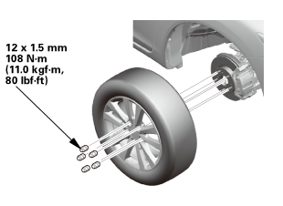
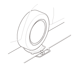
| 2. | Tire and Wheel-Removal, Front Right |
|
|
|
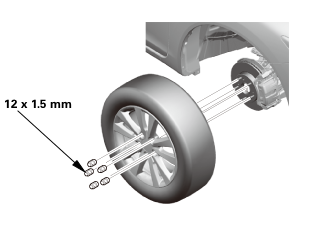 12x1mm
| 3. | ATF - Replacement |
|
|
|
 (somn)
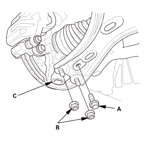
| 4. | Right Lower Ball Joint Lower Arm Side Disconnection |
|
|
|
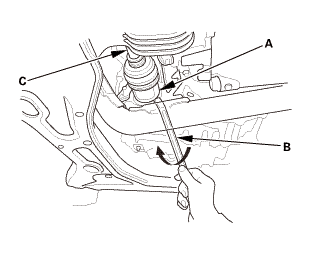
| 5. | Driveshaft Front Right, Inboard Side - Disconnection |
|
|
|
|||||||||||||||||

|
|
|
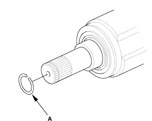
| 6. | Right Differential Oil Seal |
|
|
|
||||||
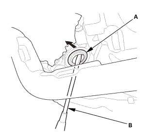

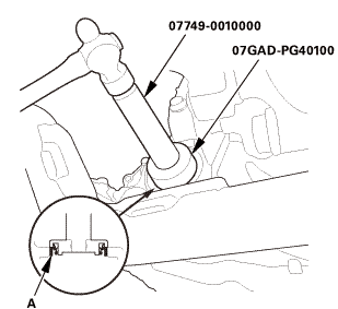
| 1. | Right Differential Oil Seal |
|
|
|
||||||
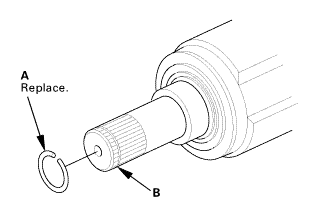
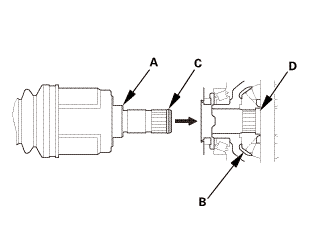
| 2. | Driveshaft Front Right, Inboard Side - Reconnection |
|
|
|
|
|
|
||||||||||||
| 3. | Right Lower Ball Joint Lower Arm Side Reconnection |
|
|
|
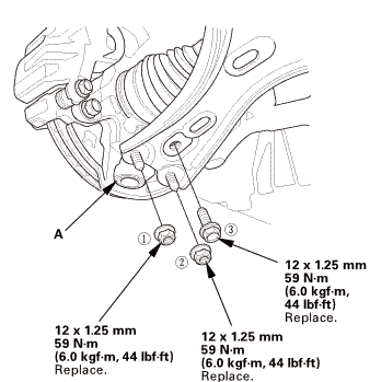 replace.
| 4. | Tire and Wheel-Installation, Front Right |
|
|
|
||||||
 mminmuan
| 5. | Driveshaft After Install Check |
|
| 6. | ATF - Replacement |
|
|
|
|
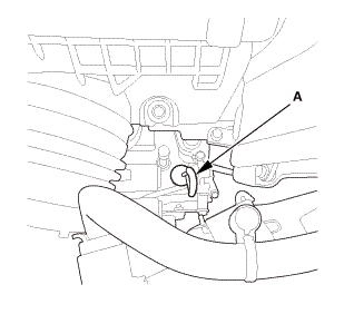
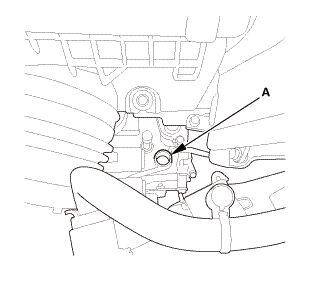
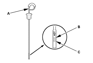
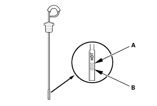
2. |
Refill the transmission with the recommended fluid into the dipstick hole (A) to bring the fluid level between the upper mark and the lower mark of the dipstick. Always use Honda automatic transmission fluid (ATF) ATF DW-1. Using a non-Honda ATF can affect shift quality. |
|||||||||
|
||||||||||
|
|
|
| 7. | Warm Up The Engine |
|
| 8. | ATF Level Check |
|
|
|
|
|
|
||||||||||||||||||||||||||||||||||
|
|
|
| 9. | Pre-Alignment Checks |
|
| 10. | Caster - Inspection |
|
|||||||||||||||||||||||||||||||||||||||||||||||
| 11. | Camber - Inspection |
|
||||||||||||||||||||||||||||||||||||||||||||||||||||||||||||||||||||||||||||||||||||||
| 12. | Front Toe - Inspection |
|
|||||||||||||||||||||||||
| 13. | Turning Angle - Inspection |
|
|
|
|||||||||||||||||||||||||||||||||||||||||||||||||||||||||||||||||||||||||||||||||||||||||
|
|
|
|||||||||||||||||||||||||||||||||||||||||||||||||||||||||
| 14. | Test Drive |
|
| 15. | Maintenance Minder Reset |
|
 Left M/T Differential Oil Seal Replacement (R18Z1 M/T)
2191F4 LEFT
1.
Vehicle Lift
1.
Raise the vehicle on a lift, and make sure it is securely supported.
...
 Right M/T Differential Oil Seal Replacement (R18Z1 M/T)
2191F5 RIGHT
1.
Vehicle Lift
1.
Raise the vehicle on a lift, and make sure it is securely supported.
...
See also:
Honda Civic Owners Manual. Protecting Smaller Children
If a child is at least one year old and within the weight range indicated by
the child
seat manufacturer, the child should be properly restrained in a firmly secured
forward-facing child seat.
Forward-facing child seat placement
We strongly recommend placing a forwardfacing
child seat in ...
