Honda Civic Service Manual: Manual Transmission Disassembly and Reassembly (R18Z1 M/T)
 View
View
| 1. |
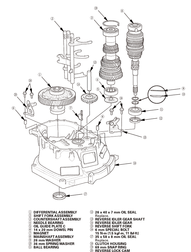
Clutch Housing Exploded View |
|
Exploded View - Clutch Housing
|
 nirrerem1alassemslvsmncoumersmar1assemalvnameoncum:u.20mmwashermminnommonsealreversegearsmmreverseidlergearevreverseforkmmbolti5mmhousingmmsunnzvznszlock
| 2. |
Transmission Housing Exploded View |
|
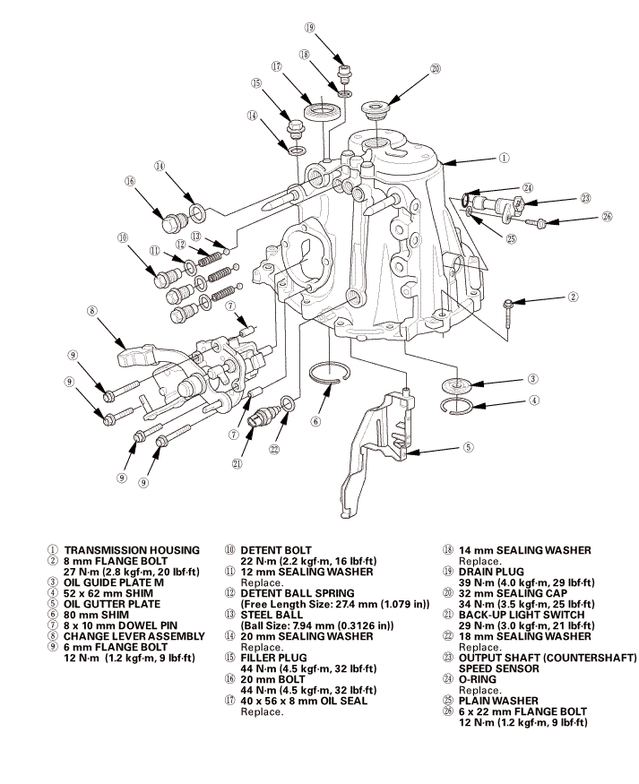
Exploded View - Transmission Housing
|
 nuusulssloumm21nmmmmummmmmsunmmpinmm12ummuneremrsunams...-ams...-(n......fillerplug2n......sou56......mumatmm......22......
 Disassembly
|
NOTE: Place the clutch housing on two pieces of wood thick enough to
keep the mainshaft from hitting the workbench.
|
| 1. |
M/T Change Lever Assembly |
|
|
|
1.
|
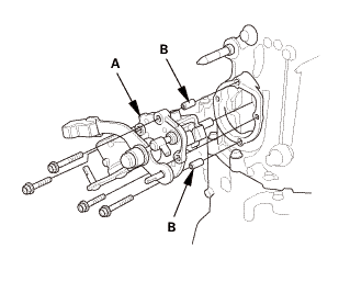
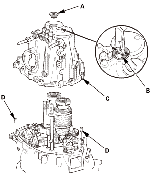
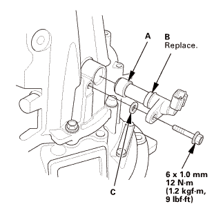
Remove the change lever assembly (A).
|
|
2.
|
Remove the 8 x 10 mm dowel pins (B).
|
|
|
|
|
1.
|
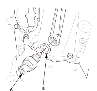
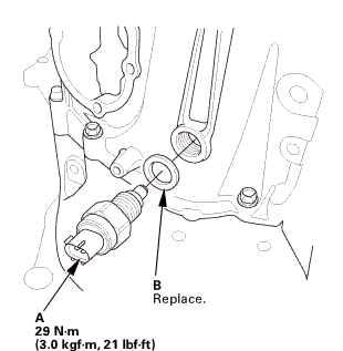
Remove the back-up light switch (A) and the 18 mm sealing washer
(B).
|
|
| 3. |
M/T Output Shaft Speed Sensor |
|
|
|
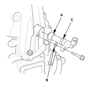
1.
|
Remove the output shaft (countershaft) speed sensor (A), the
plain washer (B), and the O-ring (C).
|
|
| 4. |
M/T Transmission Housing Assembly |
|
|
|
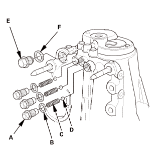
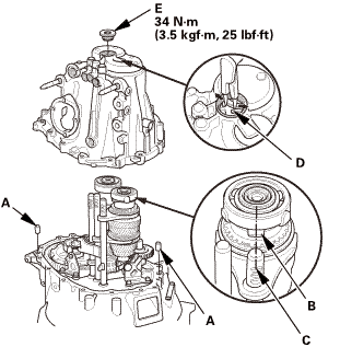
1.
|
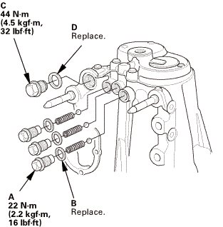
Remove the detent bolts (A), the 12 mm sealing washers (B), the
detent ball springs (C), and the steel balls (D).
|
|
2.
|
Remove the 20 mm bolt (E) and the 20 mm sealing washer (F).
|
|
|
|
|
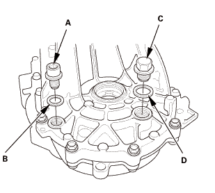
3.
|
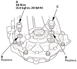
Remove the drain plug (A) and the sealing washer (B).
|
|
4.
|
Remove the filler plug (C) and the sealing washer (D).
|
|
|
|
|
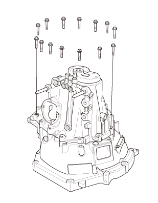
5.
|
Remove the 8 mm flange bolts in a crisscross pattern in several
steps.
|
|
|
|
|
6.
|
Remove the 32 mm sealing cap (A).
|
|
7.
|
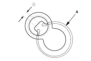
While expanding the 69 mm snap ring (B) on the countershaft ball
bearing with snap ring pliers, lift the transmission housing (C).
|
|
8.
|
Release the snap ring pliers, and remove the transmission housing.
|
|
9.
|
Remove the 14 x 20 mm dowel pins (D).
|
|
|

|
|
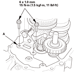
1.
|
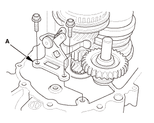
Remove the oil gutter plate (A).
|
|
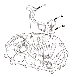
2.
|
Remove the 52 x 62 mm shim (B).
|
|
3.
|
Remove oil guide plate M.
|
|
| 6. |
M/T Reverse Shift Fork |
|
|
|
1.
|
Remove the reverse shift fork (A).
|
|
|
|
|
1.
|
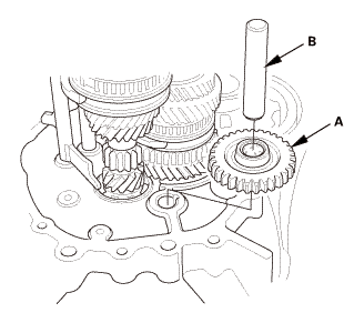
Remove the reverse idler gear (A) and the reverse idler gear
shaft (B).
|
|
|
|
|
1.
|
Remove the reverse lock cam (A).
|
|
| 9. |
M/T Mainshaft and Countershaft and Shift Fork Assembly |
|
|
|
1.
|
Apply a thin layer of tape to the mainshaft splines to protect
the seal.
|
|
NOTE: Do not apply too much tape as it will damage the oil seal.
|
|
2.
|
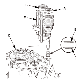
Remove the mainshaft assembly (A) and the countershaft assembly
(B) with the shift fork assembly (C) from the clutch housing (D).
|
|
3.
|
Remove the 26 mm washer (E).
|
|
4.
|
Remove the 36 mm spring washer (F).
|
|
| 10. |
Differential Assembly |
|
|
|
1.
|
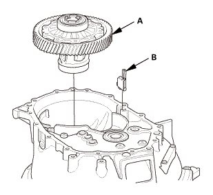
Remove the differential assembly (A).
|
|
2.
|
Remove the magnet (B).
|
|
 Reassembly
|
NOTE: Prior to reassembly, clean all parts in solvent, dry them, and
apply MTF to any contact surfaces.
|
|

|
|
1.
|
Install the magnet (A).
|
|
NOTE: Clean the magnet any time the transmission is disassembled.
|
|
2.
|
Install the differential assembly (B).
|
|
| 2. |
M/T Mainshaft and Countershaft and Shift Fork Assembly |
|
|
|
1.
|
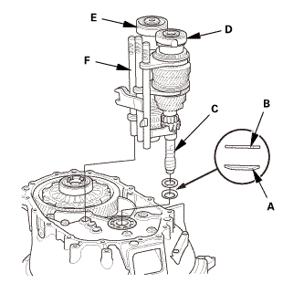
Install the 36 mm spring washer (A).
|
|
NOTE: Be sure to install the spring washer in the direction shown.
|
|
2.
|
Install the 26 mm washer (B).
|
|
3.
|
Apply a thin layer of tape to the mainshaft splines (C) to protect
the seal.
|
|
NOTE: Do not apply too much tape as it will damage the oil seal.
|
|
4.
|
Install the mainshaft assembly (D) and the countershaft assembly
(E) with the shift fork assembly (F), as an assembly.
|
|
|
|
|
1.
|
Install the reverse lock cam (A).
|
|
|
|
|
1.
|
Install the reverse idler gear (A) and the reverse idler gear
shaft (B).
|
|
| 5. |
M/T Reverse Shift Fork |
|
|
|
1.
|
Install the reverse shift fork (A).
|
|
|
|
|
1.
|
Select the proper size 52 x 62 mm shim (A) according to the measurements
made during the Mainshaft Thrust Clearance Adjustment.
|
|
2.
|
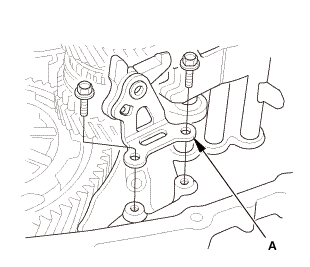
Install the oil gutter plate (B).
|
|
3.
|
Install oil guide plate M.
|
|
4.
|
Install the 52 x 62 mm shim.
|
|
| 7. |
M/T Transmission Housing Assembly |
|
1.
|
Clean any dirt or oil from the mating surface of the transmission housing
and the clutch housing.
|
|
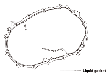
2.
|
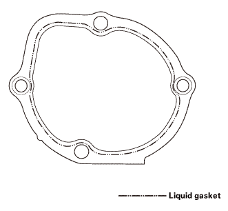
Apply liquid gasket, P/N 08717-0004, 08718-0001, 08718-0003, 08718-0004,
or 08718-0009 evenly to the clutch housing mating surface of the transmission
housing. Install the component within 5 minutes of applying the liquid gasket.
|
|
NOTE:
|
|

|
If you apply liquid gasket P/N 08718-0012, the component
must be installed within 4 minutes.
|
|
|
|
If too much time has passed after applying the liquid
gasket, remove the old liquid gasket and residue, then reapply
new liquid gasket.
|
|
|
|
 imto imto
|
|
3.
|
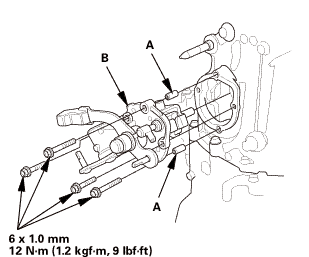
Install the 14 x 20 mm dowel pins (A).
|
|
4.
|
Set the tapered cone ring pawl (B) faces the 5th shift fork (C).
|
|
5.
|
Place the transmission housing on the clutch housing, making
sure to line up the shafts.
|
|
6.
|
While expanding the 69 mm snap ring (D) on the countershaft ball
bearing using snap ring pliers, push the transmission housing down
to start the countershaft ball bearing through the snap ring.
|
|
7.
|
Release the pliers, and push down the housing until it bottoms
out and the snap ring snaps in place in the countershaft ball bearing
snap ring groove.
|
|
NOTE: Install the 32 mm sealing cap (E) after setting in the
69 mm snap ring.
|
|
|
|
|
8.
|
Make sure the 69 mm snap ring (A) is securely seated in the groove
of the countershaft bearing.
|
|
Dimension
 as installed:
3.3-6.5 mm (0.130-0.256 in) as installed:
3.3-6.5 mm (0.130-0.256 in)
|
|
9.
|
Apply liquid gasket, P/N 08717-0004, 08718-0001, 08718-0003,
08718-0004, or 08718-0009 evenly to the threads of the 32 mm sealing
cap. Install the component within 5 minutes of applying the liquid
gasket.
|
|
NOTE:
|
|
|
If you apply liquid gasket P/N 08718-0012, the
component must be installed within 4 minutes.
|
|
|
|
If too much time has passed after applying the
liquid gasket, remove the old liquid gasket and
residue, then reapply new liquid gasket.
|
|
|
|
|
|
|
10.
|
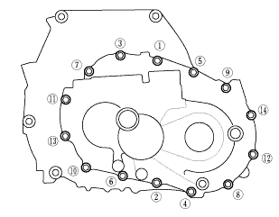
Install the 8 mm flange bolts finger-tight.
|
|
|
|
|
11.
|
Tighten the 8 mm flange bolts in a crisscross pattern in several
steps.
|
|
|
Specified Torque:
|
8 x 1.25 mm
27 N·m (2.8 kgf·m, 20 lbf·ft)
|
|
|
|
|
|
|
|
12.
|
Install the drain plug (A) with a new sealing washer (B).
|
|
13.
|
Install the filler plug (C) with a new sealing washer (D) finger-tight.
|
|
|
|
|
14.
|
Install the steel balls, the detent ball springs, and the detent
bolts (A) with new 12 mm sealing washers (B).
|
|
15.
|
Install the 20 mm bolt (C) with a new 20 mm sealing washer (D).
|
|
| 8. |
M/T Output Shaft Speed Sensor |
|
|
|
1.
|
Install the output shaft (countershaft) speed sensor (A) with
a new O-ring (B) and the plain washer (C).
|
|
|
|
|
1.
|
Install the back-up light switch (A) with a new 18 mm sealing
washer (B).
|
|
| 10. |
M/T Change Lever Assembly |
|
 -mid -mid
|
|
1.
|
Clean any dirt or oil from the mating surface of the change lever
assembly and the transmission housing.
|
|
2.
|
Apply liquid gasket, P/N 08717-0004, 08718-0001, 08718-0003,
08718-0004, or 08718-0009 evenly to the transmission housing mating
surface of the change lever assembly. Install the component within
5 minutes of applying the liquid gasket.
|
|
NOTE:
|
|
|
If you apply liquid gasket P/N 08718-0012, the
component must be installed within 4 minutes.
|
|
|
|
If too much time has passed after applying the
liquid gasket, remove the old liquid gasket and
residue, then reapply new liquid gasket.
|
|
|
|
|
 .omm-m(i.2kvf-m.9bm1! .omm-m(i.2kvf-m.9bm1!
|
|
3.
|
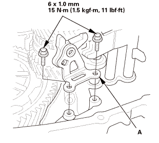
Install the 8 x 10 mm dowel pins (A).
|
|
4.
|
Install the change lever assembly (B).
|
|
1.
Vehicle Lift
1.
Raise the vehicle on a lift, and make sure it is securely supported.
...
111145 TRANSMISSION SIDE
Removal
1.
Pressure Plate
1.
Install the ring gear holder.
...
See also:
Honda Civic Owners Manual. Installing a LATCH-Compatible Child Seat
A LATCH-compatible child seat can be installed in either of the two outer
rear seats.
A child seat is attached to the lower anchors with either the rigid or flexible
type of
connectors.
1. Locate the lower anchors under the marks.
2. Place the child seat on the vehicle seat then
a ...
 MTF Replacement (M/T)
 Manual Transmission End Crankshaft Oil Seal Replacement - In Car (R18Z1 M/T)