Honda Civic Service Manual: Engine Oil Jet and Bolt Inspection (K24Z7)

| 1. | Warm Up The Engine |
|
| 2. | Vehicle Lift |
|
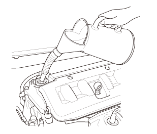
| 3. | Engine Oil - Replacement |
|
|
|
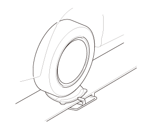
| 4. | Front Wheel |
|
|
|
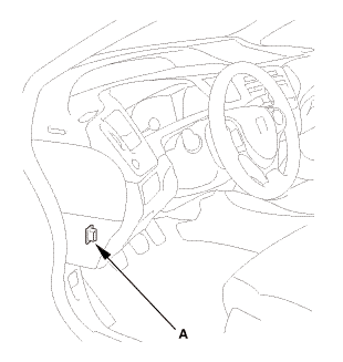
| 5. | Steering Joint Cover |
|
|
|
| 6. | Steering Column Lower Slide Shaft - Hold |
|
|
|
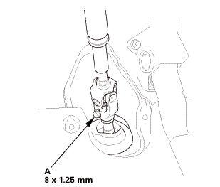
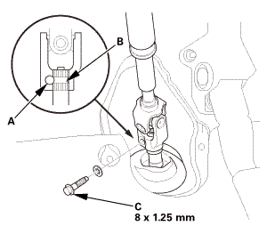
| 7. | Steering Joint Bolt - Loosen |
|
|
|
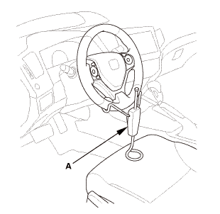
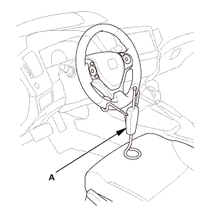
| 8. | Steering Wheel Hold |
|
|
|
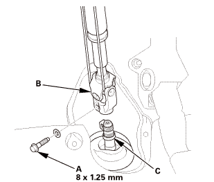
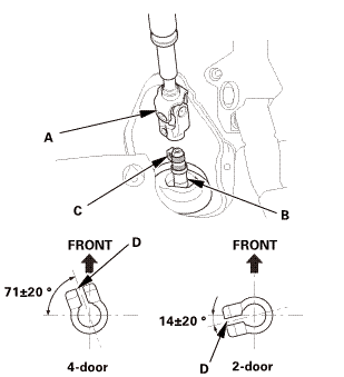
| 9. | Steering Joint - Disconnection |
|
|
|
||||||||||||||||||||

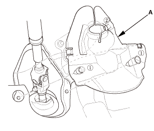
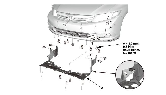
| 10. | Splash Shield |
|
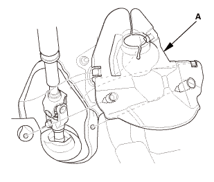
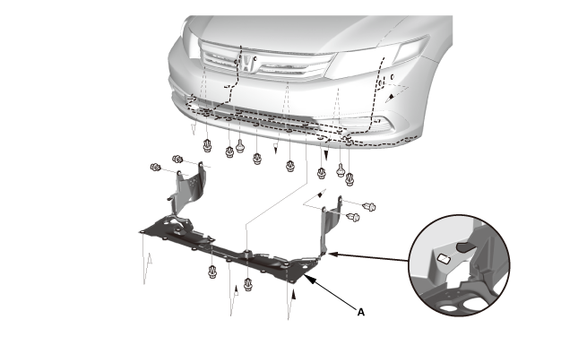
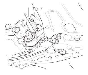
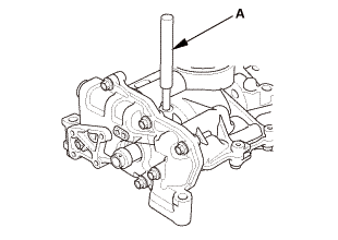
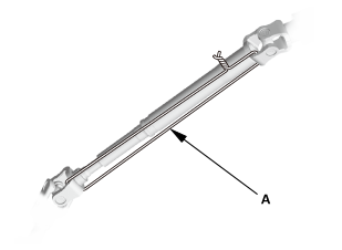
1. |
Remove the splash shield (A). |
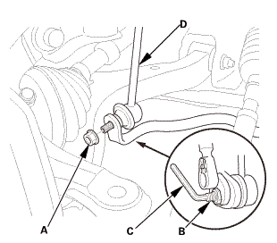
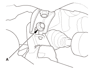
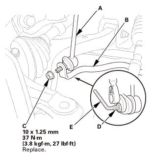
| 11. | Front Stabilizer Ball Joint - Disconnection, Both Lower Arm Side |
|
|
|
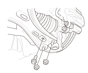
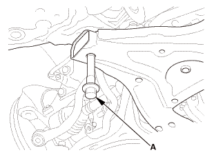
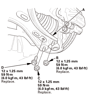
| 12. | Lower Arm Joint - Disconnection, Both Knuckle Side |
|
|
|
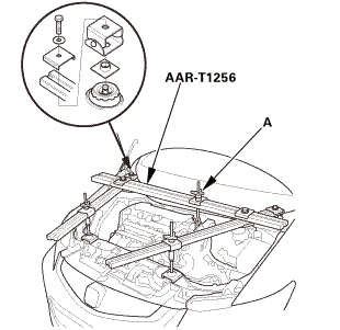
| 13. | Engine Support Hanger |
|
|
|
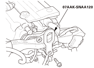 o7aaksnaai2o
|
|
|
||||||||||||
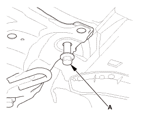
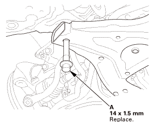
| 14. | Lower Torque Rod - Disconnection |
|
|
|
| 15. | Front Sub Frame - Move |
|
|
|
|
FRONT
REAR
|
|
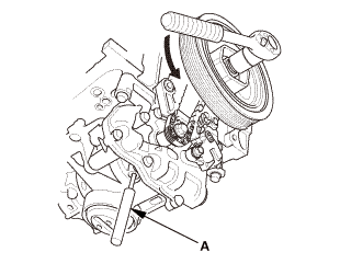
| 16. | Crankshaft Pulley - Turn |
|
|
|
||||||
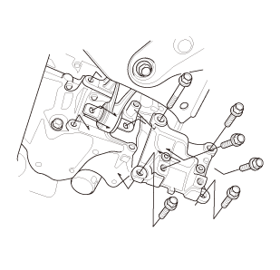
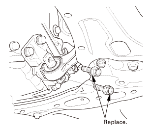
| 17. | Lower Torque Rod Bracket |
|
|
|
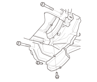
| 18. | Clutch Cover |
|
|
|
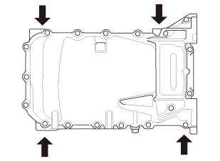
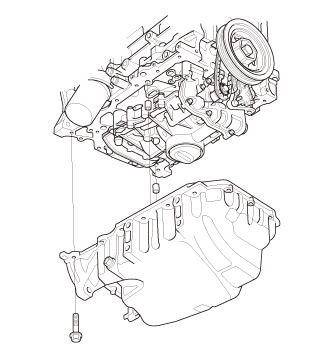
| 19. | Oil Pan Assembly |
|
|
|
|
|
|
| 20. | Oil Pump Chain Tensioner |
|
|
|
|
|
|
|
|
|
| 21. | Engine Oil Pump Assembly |
|
|
|
|
|
|
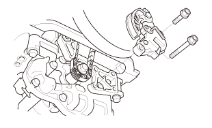
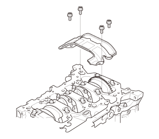
| 22. | Engine Baffle Plate |
|
|
|
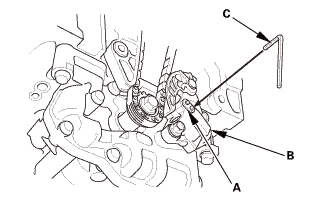
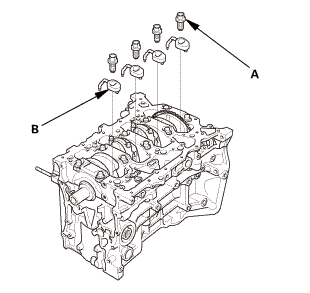
| 23. | Engine Oil Jet |
|
|
|

| 1. | Engine Oil Jet and Bolt - Inspection |
|
|
|
|||||||||||||||||||||
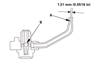

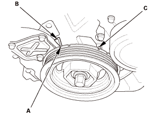
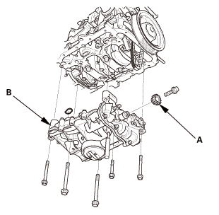
| 1. | Engine Oil Jet |
|
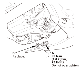
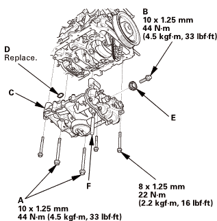
1. |
Carefully install the oil jets (A) and the oil jet bolts (B). |
 n.75mmis
| 2. | Engine Baffle Plate |
|
|
|
| 3. | Crankshaft Pulley - Turn |
|
|
|
||||||
| 4. | Engine Oil Pump Assembly |
|
|
|
|
|
|
|
|
|
 u....2:...u....
| 5. | Oil Pump Chain Tensioner |
|
|
|
| 6. | Oil Pan Assembly |
|
|
|
||||||||||||||||||||||||||
|
|
|
|||||||||||||||||
| 7. | Clutch Cover |
|
|
|
| 8. | Lower Torque Rod Bracket |
|
|
|
| 9. | Front Sub Frame - Move |
|
REAR
FRONT
|
|
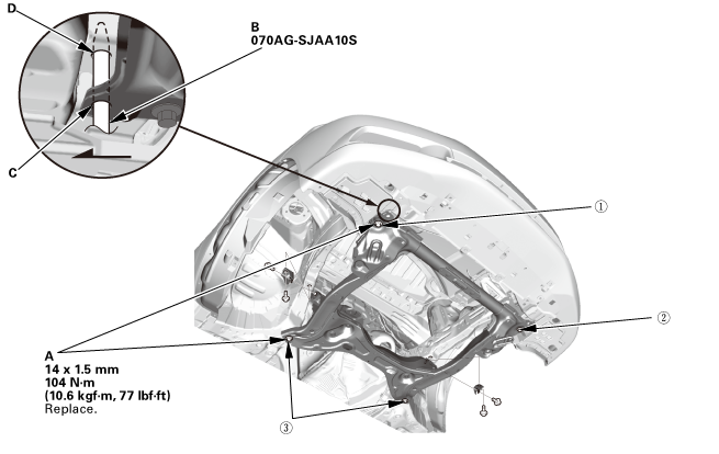
| 10. | Front Subframe Assembly |
|
1. |
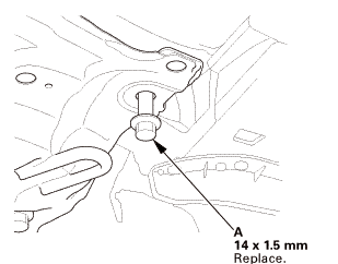
Loosely install the new front subframe mounting bolts (A). |
 n-m77lm41!
|
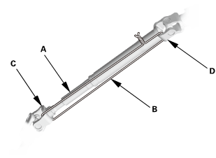
2. |
Insert the subframe alignment pin (B) through the positioning hole (C) on the right front subframe, and into the positioning hole (D) on the body, then loosely tighten the subframe right front mounting bolt. |
|
3. |
Insert the subframe alignment pin through the positioning slot on the left front subframe, and into the positioning hole on the body, then loosely tighten the subframe left front mounting bolt. |
|
4. |
Tighten the subframe mounting bolts to the specified torque values starting with the right front subframe mounting bolt. Use the subframe alignment pin when tightening the front side subframe mounting bolts. |
|
5. |
Check all of the subframe mounting bolts, and retighten if necessary. |
|
|
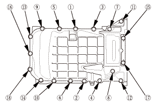
NOTE: Tighten the bolts in the sequence shown. |
||
| 11. | Lower Torque Rod - Reconnection |
|
|
|
| 12. | Engine Support Hanger |
|
|
|
| 13. | Lower Arm Joint - Reconnection, Both Knuckle Side |
|
|
|
 mm
mm| 14. | Front Stabilizer Ball Joint - Reconnection, Both Lower Arm Side |
|
|
|
 27m.27
| 15. | Steering Column Lower Slide Shaft - Release |
|
|
|
| 16. | Steering Wheel Release |
|
|
|
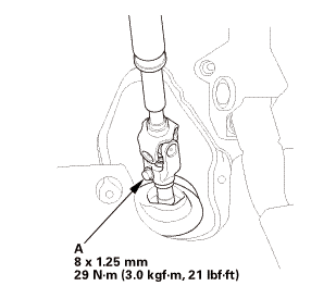
| 17. | Steering Joint - Reconnection |
|
|
|
||||||||||||||||||||
|
|
|
| 18. | Steering Joint Bolt - Tighten |
|
|
|
 mm:.o21
| 19. | Steering Joint Cover |
|
|
|
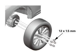
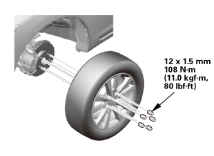
| 20. | Front Wheel |
|
|
|
||||||
 mmmln-mnomm
| 21. | Engine Oil - Replacement |
|
|
|
|||||||||||||||||||||||||||||
| 22. | Splash Shield |
|
1. |
Install the splash shield (A). |
| 23. | Pre-Alignment Checks |
|
| 24. | Caster - Inspection |
|
|||||||||||||||||||||||||||||||||||||||||||||||
| 25. | Camber - Inspection |
|
||||||||||||||||||||||||||||||||||||||||||||||||||||||||||||||||||||||||||||||||||||||
| 26. | Front Toe - Inspection |
|
|||||||||||||||||||||||||
| 27. | Turning Angle - Inspection |
|
|
|
|||||||||||||||||||||||||||||||||||||||||||||||||||||||||||||||||||||||||||||||||||||||||
|
|
|
|||||||||||||||||||||||||||||||||||||||||||||||||||||||||
| 28. | HDS DLC - Connection |
|
|
|
| 29. | VSA Sensor Neutral Position - Memorization |
|
||||||||||
| 30. | Steering Angle Sensor Neutral Position - Clear |
|
|||||||
| 31. | Maintenance Minder Reset |
|
 Engine Oil Jet Removal and Installation (K24Z7)
1.
Warm Up The Engine
1.
Warm up the engine.
2.
Vehicle Lift
...
 Engine Oil Jet and Bolt Inspection (R18A9)
Removal
1.
Intake Manifold and Throttle Body Assembly (Natural Gas Model)
1.
Remove the intake air duct.
...
See also:
Honda Civic Owners Manual. Automatic Seat Belt Tensioners
The front seats are equipped with automatic seat belt tensioners to enhance
safety.
The tensioners automatically tighten the front seat belts during a moderate-tosevere
frontal collision, sometimes even if the collision is not severe enough to
inflate the front airbags.
Automatic Seat Be ...
