Honda Civic Service Manual: Engine Oil Jet Removal and Installation (K24Z7)

| 1. | Warm Up The Engine |
|
| 2. | Vehicle Lift |
|
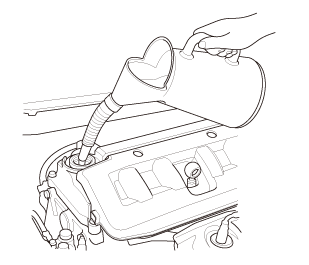
| 3. | Engine Oil - Replacement |
|
|
|
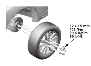
| 4. | Front Wheel |
|
|
|
| 5. | Steering Joint Cover |
|
|
|
| 6. | Steering Column Lower Slide Shaft - Hold |
|
|
|
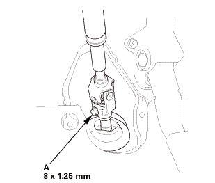
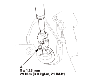
| 7. | Steering Joint Bolt - Loosen |
|
|
|
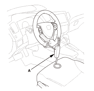
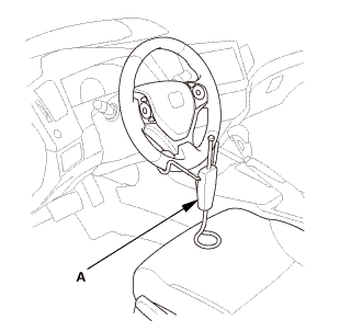
| 8. | Steering Wheel Hold |
|
|
|
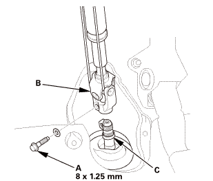
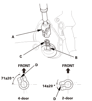
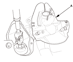
| 9. | Steering Joint - Disconnection |
|
|
|
||||||||||||||||||||

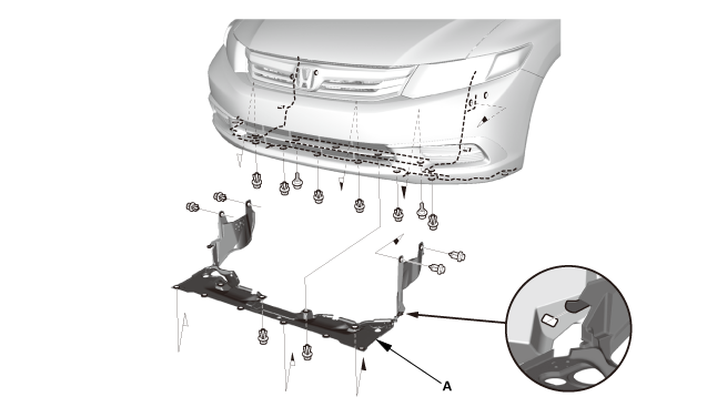
| 10. | Splash Shield |
|
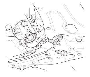
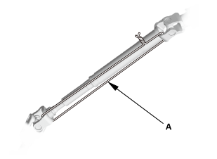
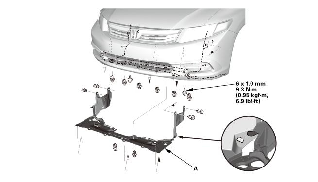
1. |
Remove the splash shield (A). |
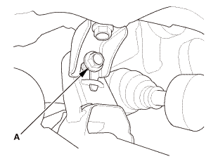
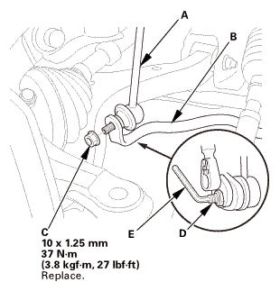
| 11. | Front Stabilizer Ball Joint - Disconnection, Both Lower Arm Side |
|
|
|
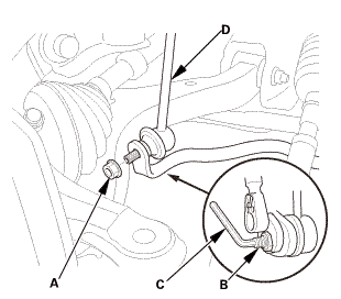
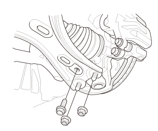
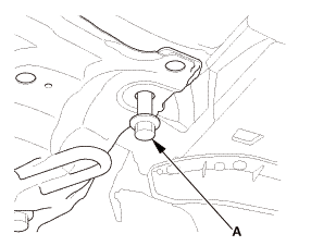
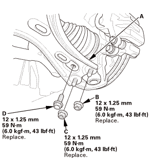
| 12. | Lower Arm Joint - Disconnection, Both Knuckle Side |
|
|
|
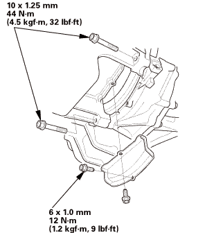
| 13. | Engine Support Hanger |
|
|
|
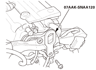 o7aaksnaai2o
|
|
|
||||||||||||
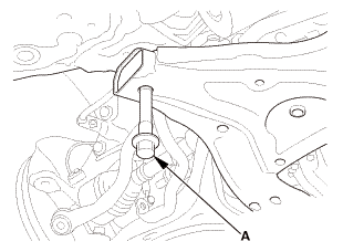
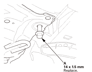
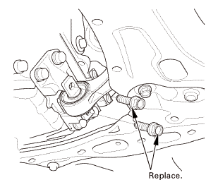
| 14. | Lower Torque Rod - Disconnection |
|
|
|
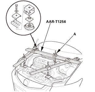
| 15. | Front Sub Frame - Move |
|
|
|
|
FRONT
REAR
|
|
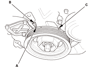
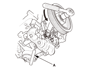
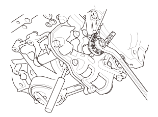
| 16. | Crankshaft Pulley - Turn |
|
|
|
||||||
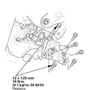
| 17. | Lower Torque Rod Bracket |
|
|
|
| 18. | Clutch Cover |
|
|
|
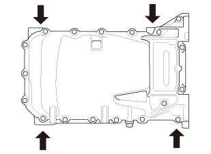
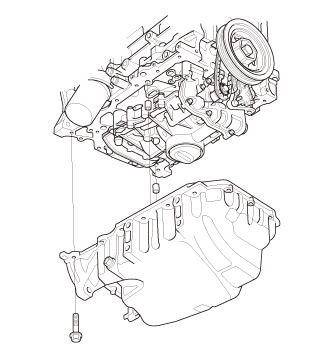
| 19. | Oil Pan Assembly |
|
|
|
|
|
|
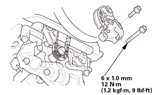
| 20. | Oil Pump Chain Tensioner |
|
|
|
|
|
|
|
|
|
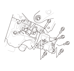
| 21. | Engine Oil Pump Assembly |
|
|
|
|
|
|
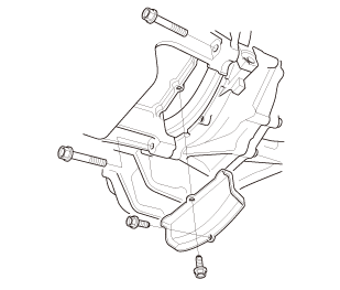
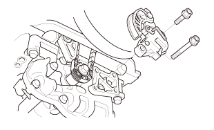
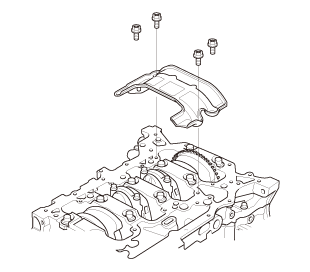
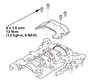
| 22. | Engine Baffle Plate |
|
|
|
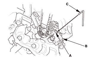
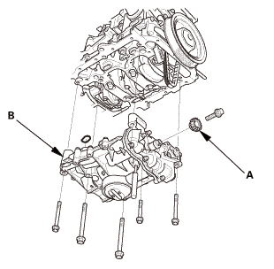
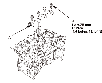
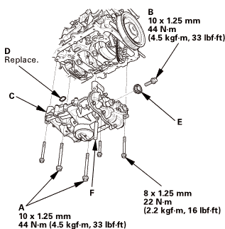
| 23. | Engine Oil Jet |
|
|
|
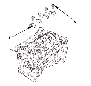

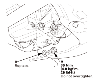
| 1. | Engine Oil Jet |
|
1. |
Carefully install the oil jets (A) and the oil jet bolts (B). |
 n.75mmis
| 2. | Engine Baffle Plate |
|
|
|
| 3. | Crankshaft Pulley - Turn |
|
|
|
||||||
| 4. | Engine Oil Pump Assembly |
|
|
|
|
|
|
|
|
|
 u....2:...u....
| 5. | Oil Pump Chain Tensioner |
|
|
|
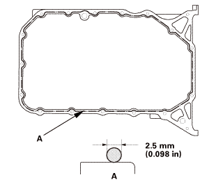
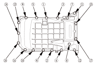
| 6. | Oil Pan Assembly |
|
|
|
||||||||||||||||||||||||||
|
|
|
|||||||||||||||||
| 7. | Clutch Cover |
|
|
|
| 8. | Lower Torque Rod Bracket |
|
|
|
| 9. | Front Sub Frame - Move |
|
REAR
FRONT
|
|
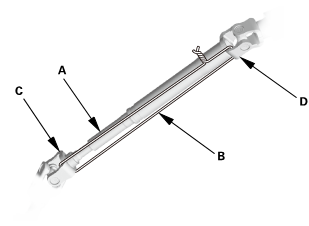
| 10. | Front Subframe Assembly |
|
1. |
Loosely install the new front subframe mounting bolts (A). |
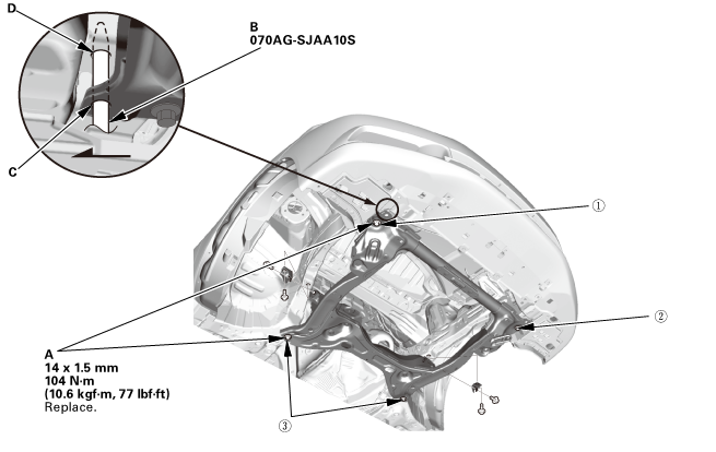 n-m77lm41!
|
2. |
Insert the subframe alignment pin (B) through the positioning hole (C) on the right front subframe, and into the positioning hole (D) on the body, then loosely tighten the subframe right front mounting bolt. |
|
3. |
Insert the subframe alignment pin through the positioning slot on the left front subframe, and into the positioning hole on the body, then loosely tighten the subframe left front mounting bolt. |
|
4. |
Tighten the subframe mounting bolts to the specified torque values starting with the right front subframe mounting bolt. Use the subframe alignment pin when tightening the front side subframe mounting bolts. |
|
5. |
Check all of the subframe mounting bolts, and retighten if necessary. |
|
|
NOTE: Tighten the bolts in the sequence shown. |
||
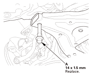
| 11. | Lower Torque Rod - Reconnection |
|
|
|
| 12. | Engine Support Hanger |
|
|
|
| 13. | Lower Arm Joint - Reconnection, Both Knuckle Side |
|
|
|
 mm
mm| 14. | Front Stabilizer Ball Joint - Reconnection, Both Lower Arm Side |
|
|
|
 27m.27
| 15. | Steering Column Lower Slide Shaft - Release |
|
|
|
| 16. | Steering Wheel Release |
|
|
|
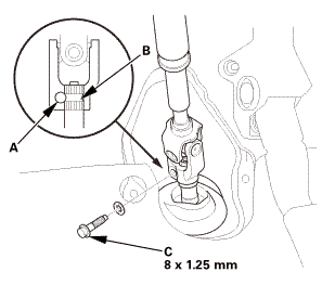
| 17. | Steering Joint - Reconnection |
|
|
|
||||||||||||||||||||
|
|
|
| 18. | Steering Joint Bolt - Tighten |
|
|
|
 mm:.o21
| 19. | Steering Joint Cover |
|
|
|
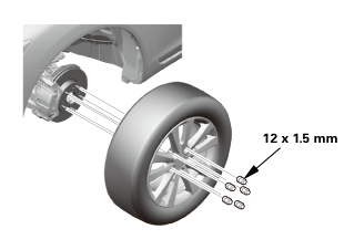
| 20. | Front Wheel |
|
|
|
||||||
 mmmln-mnomm
| 21. | Engine Oil - Replacement |
|
|
|
|||||||||||||||||||||||||||||
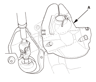
| 22. | Splash Shield |
|
1. |
Install the splash shield (A). |
| 23. | Pre-Alignment Checks |
|
| 24. | Caster - Inspection |
|
|||||||||||||||||||||||||||||||||||||||||||||||
| 25. | Camber - Inspection |
|
||||||||||||||||||||||||||||||||||||||||||||||||||||||||||||||||||||||||||||||||||||||
| 26. | Front Toe - Inspection |
|
|||||||||||||||||||||||||
| 27. | Turning Angle - Inspection |
|
|
|
|||||||||||||||||||||||||||||||||||||||||||||||||||||||||||||||||||||||||||||||||||||||||
|
|
|
|||||||||||||||||||||||||||||||||||||||||||||||||||||||||
| 28. | HDS DLC - Connection |
|
|
|
| 29. | VSA Sensor Neutral Position - Memorization |
|
||||||||||
| 30. | Steering Angle Sensor Neutral Position - Clear |
|
|||||||
| 31. | Maintenance Minder Reset |
|
 Engine Oil Filter Removal and Installation (Except K24Z7)
1111B5
1.
Vehicle Lift
1.
Raise the vehicle on a lift, and make sure it is securely supported.
...
 Engine Oil Jet and Bolt Inspection (K24Z7)
1.
Warm Up The Engine
1.
Warm up the engine.
2.
Vehicle Lift
...
See also:
Honda Civic Service Manual. Trunk Lid Lock Cylinder Removal and Installation (KC 2-door DX models,
4-door DX models)
823110
Removal
1.
Trunk Lid Trim Panel
1.
For some models: Remove the trunk lid trim panel (A).
2.
Re ...
