Honda Civic Service Manual: Dashboard/Steering Hanger Beam Removal and Installation (Natural Gas models)
8411J6

| 1. | Battery Terminal (SRS) - Disconnection |
|
|
|
||||||||||||||||||||||||||||||

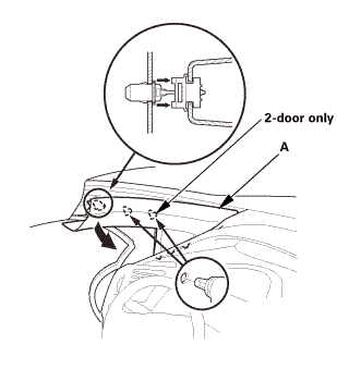
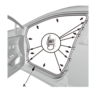
| 2. | Front Door Opening Seal As Needed Both |
|
|
|

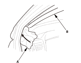
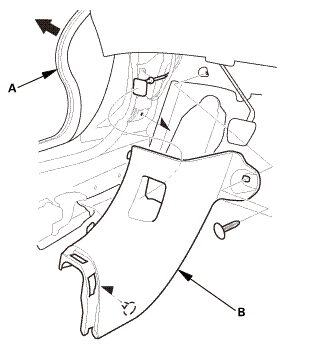
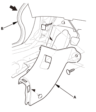
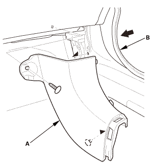
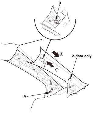
| 3. | A-Pillar Trim Both |
|
|
|
|
|
|
|
|
|
||||||
|
|
|
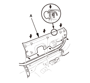
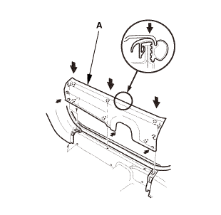
| 4. | Driver's Dashboard Lower Cover |
|
|
|
| 5. | Both Front Door Sill Trims |
|
|
|

|
|
|
|
Driver's side
Passenger's side
|
|

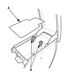
| 6. | Both Kick Panels |
|
Driver's side
Passenger's side
|
|
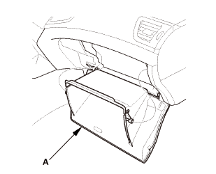
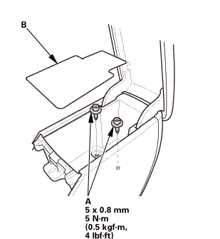
| 7. | Glove Box - Move |
|
|
|
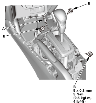
| 8. | Center Console Panel Assembly (Except '12M M/T) |
|
|
|
|
|
|
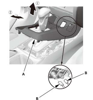
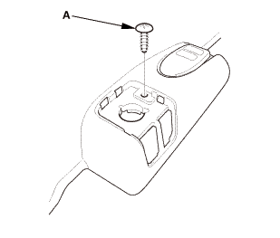
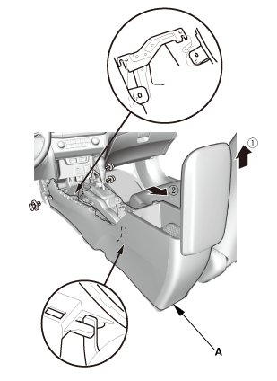
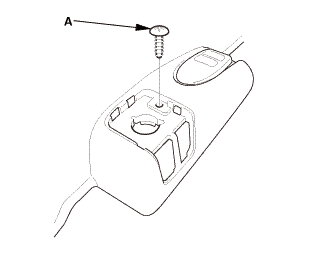
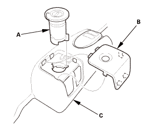
| 9. | Cup Holder Panel Assembly |
|
|
|
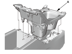
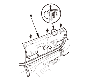
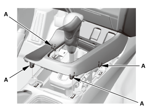
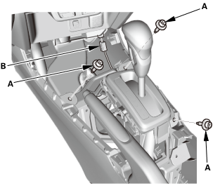
| 10. | Center Console |
|
|
|
|
|
|
|
|
|
|
|
|
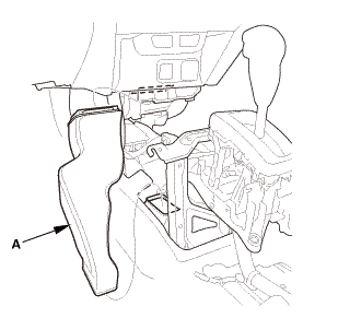
| 11. | Rear Heater Joint Duct |
|
|
|
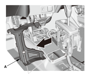
| 12. | Center Console Base Bracket |
|
|
|
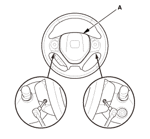
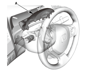
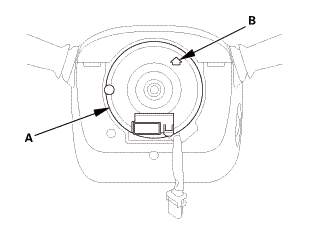
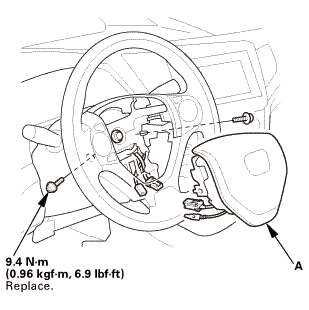
| 13. | Driver's Airbag |
|
|
|
|
|
|
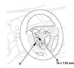
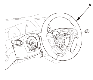
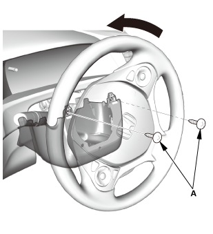
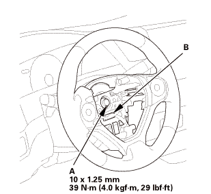
| 14. | Steering Wheel Assembly |
|
|
|
 wxusmm
|
|
|
||||||||||||||||||||
|
|
|
| 15. | Upper Column Cover |
|
|
|
| 16. | Lower Column Cover |
|
|
|
|
|
|
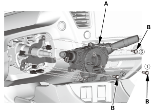
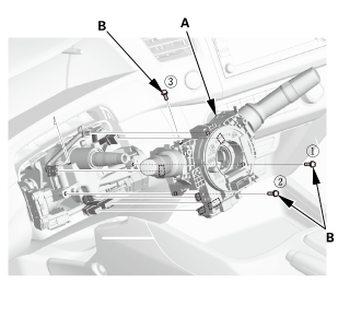
| 17. | Combination Switch Body Assembly |
|
|
|
|
|
|
|
Without steering lock
With steering lock
|
|
| 18. | Steering Joint Cover |
|
|
|
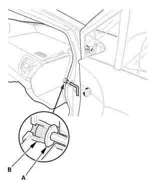
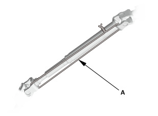
| 19. | Steering Column Lower Slide Shaft - Hold |
|
|
|
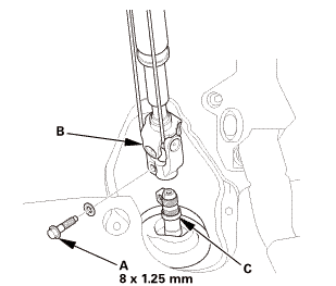
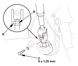
| 20. | Steering Joint Bolt - Loosen |
|
|
|
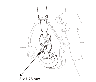
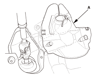
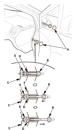
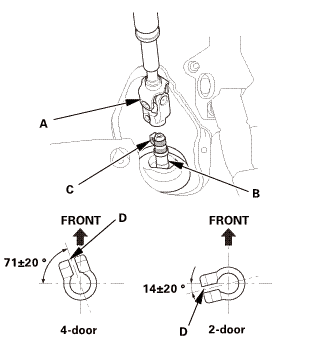
| 21. | Steering Joint - Disconnection |
|
|
|
||||||||||||||||||||
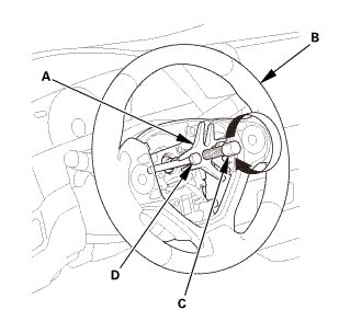
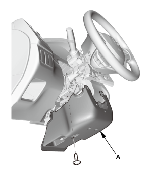
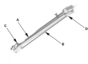
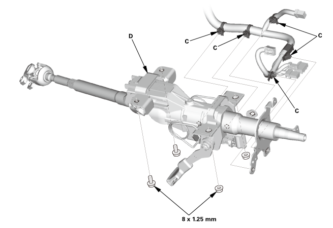
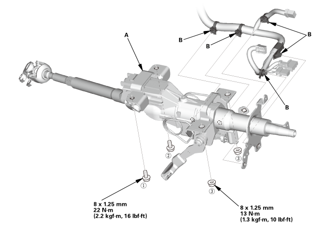
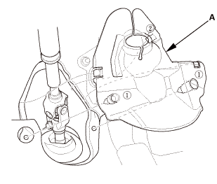
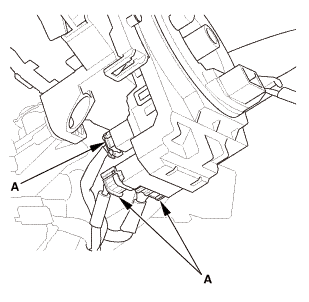
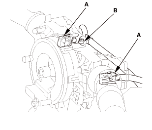
| 22. | Steering Column |
|
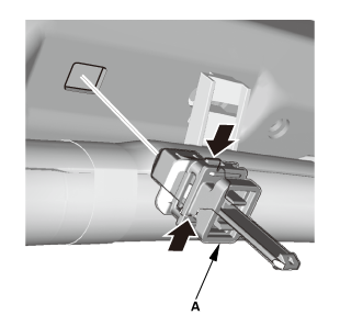
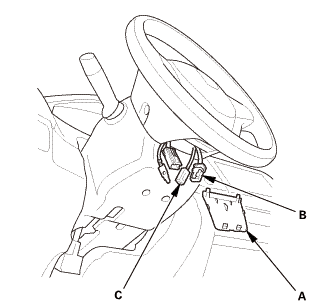
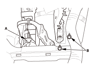
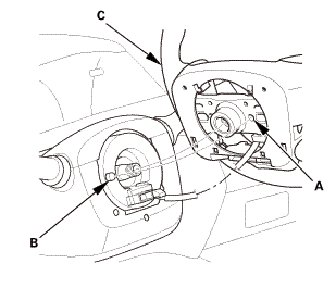
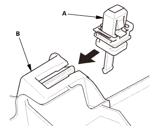
1. |
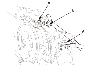
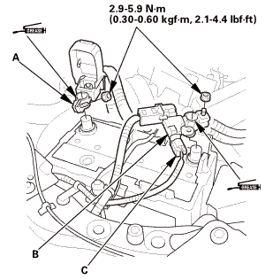
With steering lock: Disconnect the connectors (A) from the ignition switch (B). |
Without steering lock
With steering lock
|
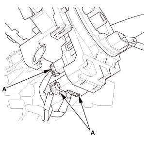
2. |
Detach the wire harness clips (C) from the steering column. |
|
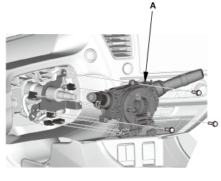
3. |
Remove the steering column (D). |
|
|
NOTE: Do not release the lock lever until the steering column is installed. If the lock lever is released before installation, adjust the steering column after installation. |
||
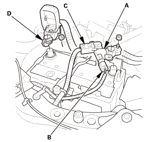
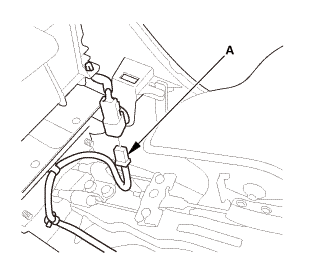
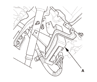
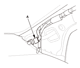
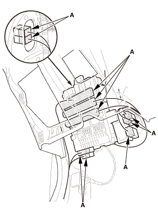
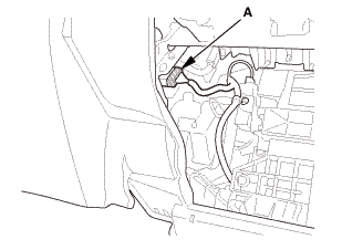
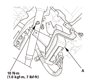
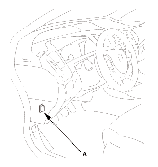
| 23. | Injector Control Module (Natural Gas Model) |
|
|
|
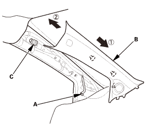
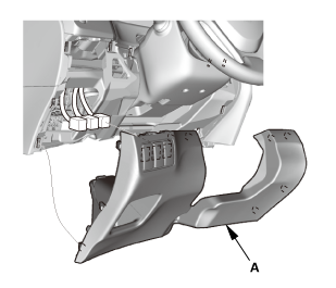
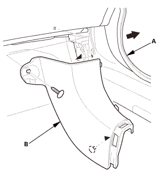
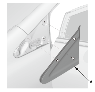
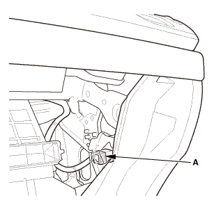
| 24. | A-Pillar Corner Trim Both |
|
|
|
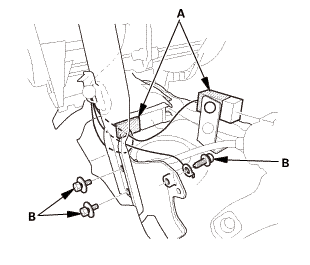
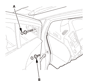
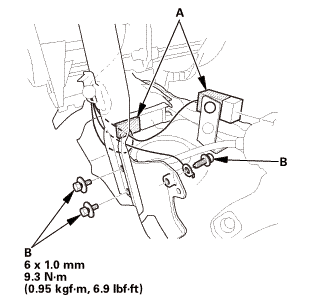
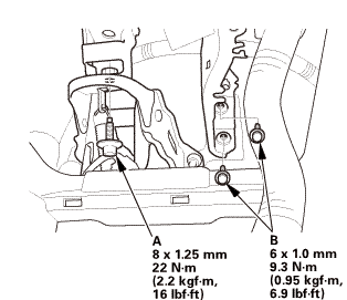
| 25. | Dashboard/Steering Hanger Beam |
|
|
|
|
|
|
|
|
|
|
|
|
|
|
|
|
|
|
|
|
|
|
|
|
|
|
|
||||||
|
|
|
|
|
|

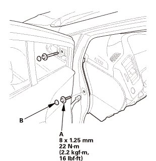
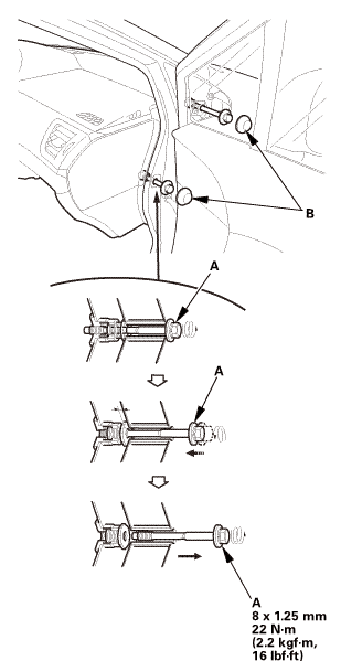
| 1. | Dashboard/Steering Hanger Beam |
|
Special bolt tightening on passenger's side
|
|
 mm22(2.2
|
|
|

|
|
|
|
|
|
|
|
|
|
|
|
|
|
|
 mmmm
mmmm|
|
|
|
|
|
 ixi2mm22(2.2asin
|
|
|

|
|
|
| 2. | A-Pillar Corner Trim Both |
|
|
|
| 3. | Injector Control Module (Natural Gas Model) |
|
|
|
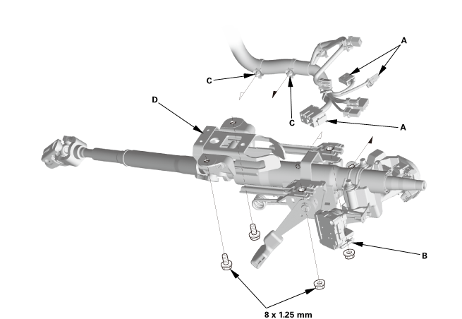
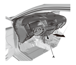
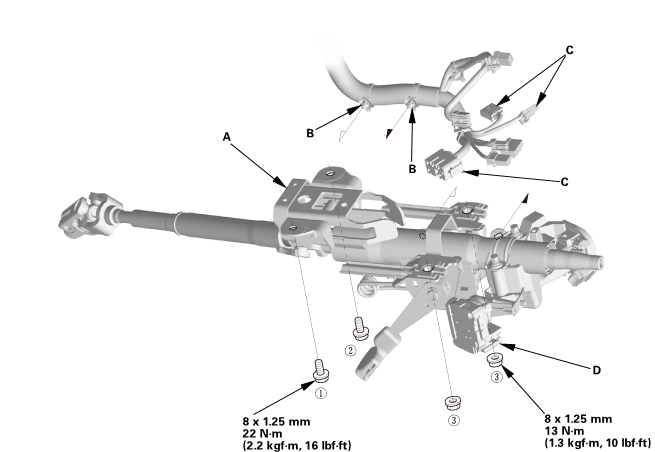
| 4. | Steering Column |
|
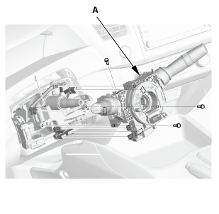
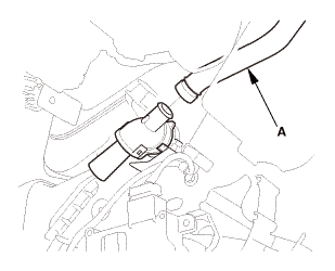
1. |
Install the steering column (A). |
|
|
NOTE: Do not release the lock lever until the steering column is installed. If the lock lever is released before installation, adjust the steering column after installation. |
||
Without steering lock
 22(22mm)
With steering lock
 u.
u.
|
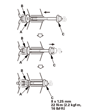
2. |
Loosely tighten the attaching nuts and bolts. |
|
3. |
Tighten the attaching nuts and bolts to the specified torque in the sequence shown. |
|
4. |
Install the wire harness clips (B) to the steering column. |
|
5. |
With steering lock: Connect the connectors (C) to the ignition switch (D). |
| 5. | Steering Joint - Reconnection |
|
|
|
||||||||||||||||||||
|
|
|
| 6. | Steering Joint Bolt - Tighten |
|
|
|
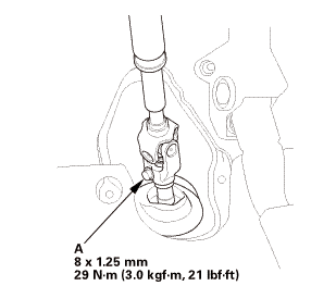 mm:.o21
| 7. | Steering Column Lower Slide Shaft - Release |
|
|
|
| 8. | Steering Joint Cover |
|
|
|
| 9. | Combination Switch Body Assembly |
|
Without steering lock
With steering lock
|
|
|
|
|
|
|
|
| 10. | Lower Column Cover |
|
|
|
|
|
|
| 11. | Upper Column Cover |
|
|
|

| 12. | Steering Wheel Assembly |
|
|
|
|
|
|
|||||||||
|
|
|
 no
no| 13. | Driver's Airbag |
|
|
|
||||||||||
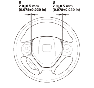 mmmmin)in!
|
|
|
||||||||||||

| 14. | Center Console Base Bracket |
|
|
|

| 15. | Rear Heater Joint Duct |
|
|
|
| 16. | Center Console |
|
|
|

|
|
|
|
|
|
|
|
|
| 17. | Cup Holder Panel Assembly |
|
|
|
| 18. | Center Console Panel Assembly (Except '12M M/T) |
|
|
|

|
|
|
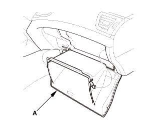
| 19. | Glove Box - Move |
|
|
|
| 20. | Both Kick Panels |
|
Driver's side
Passenger's side
|
|
| 21. | Both Front Door Sill Trims |
|
Driver's side
Passenger's side
|
|
|
|
|
|
|
|
| 22. | Driver's Dashboard Lower Cover |
|
|
|
| 23. | A-Pillar Trim Both |
|
|
|
|
|
|
||||||||||||||||||||||||||||||
| 24. | Front Door Opening Seal as Needed Both |
|
|
|
| 25. | Battery Terminal (SRS) - Reconnection |
|
|
|
|||||||||||||||||||
 (o.2ao.sam.
| 26. | HDS DLC - Connection |
|
|
|
| 27. | DTC - Clear |
|
| 28. | Confirm Proper SRS Operation |
|
| 29. | VSA Sensor Neutral Position - Memorization |
|
||||||||||
| 30. | Steering Angle Sensor Neutral Position - Clear |
|
|||||||
 Dashboard/Steering Hanger Beam Disassembly and Reassembly (Without Navigation)
SRS components are located in this area. Review the SRS component locations
and the precautions and procedures before doing repairs or service.
1.
Dashboard Su ...
 Driver's Outer Vent Removal and Installation ('13-'14)
1.
Driver's Outer Vent
1.
Remove the driver's outer vent (A).
...
See also:
Honda Civic Owners Manual. Devices that Emit Radio Waves
The following products and systems on your vehicle emit radio waves when in
operation.
Audio System
Bluetooth Audio
Bluetooth HandsFreeLink
Collision Mitigation Braking SystemTM*
Immobilizer System
Keyless Access System*
Remote Transmitter
Wireless charger
Each of ...
