Honda Civic Service Manual: A/T Gear Position Indicator Panel Light Harness Removal and Installation (A/T,
CVT)

|
NOTE: Do not wipe off the special grease applied to the area of the shift
lever marked with an asterisk (*) when you disassemble it.
|
| 1. |
Center Console Panel Assembly (Except '12M M/T) |
|
|
|
2.
|
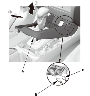
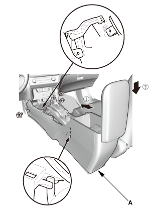
Remove the center console panel (A).
|
|
3.
|
For some models: Disconnect the connector(s) (B).
|
|
| 2. |
Cup Holder Panel Assembly |
|
|
|
1.
|
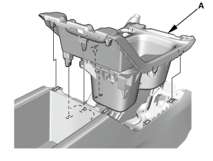
Remove the cup holder panel assembly (A).
|
|
| 3. |
Center Console Assembly |
|
|
|
2.
|
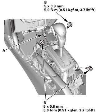
Disconnect the connector (B).
|
|
|
|
|
3.
|
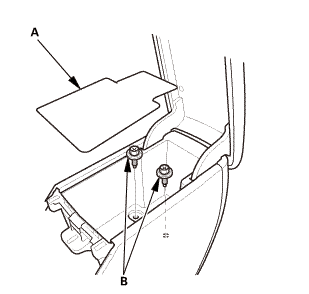
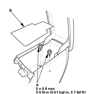
Remove the console box mat (A).
|
|
|
|
|
5.
|
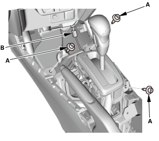
Disconnect the connector (A).
|
|
|

|
|
6.
|
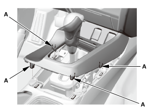
Remove the center console (A), in the numbered sequence shown.
|
|
| 4. |
Shift Lever Knob and Shift Lever Knob Ring |
|
|
|
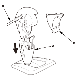
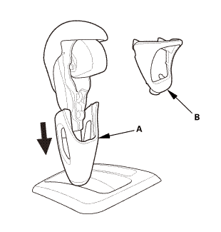
1.
|
Pull down the shift lever ring (A).
|
|
2.
|
Wrap the end of a flat-tip screwdriver (B) with tape, remove
the shift lever knob ring (C).
|
|
|
|
|
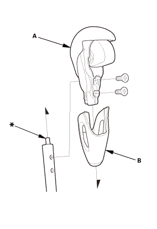
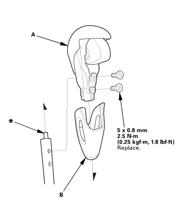
3.
|
Remove the shift lever knob (A) and the shift lever ring (B).
|
|
| 5. |
A/T Gear Position Indicator Panel Assembly (Type B Shift Lever) |
|
|
|
1.
|
Remove the A/T gear position indicator panel light socket (A).
|
|
2.
|
Remove the A/T gear position indicator panel light bulb (B).
|
|
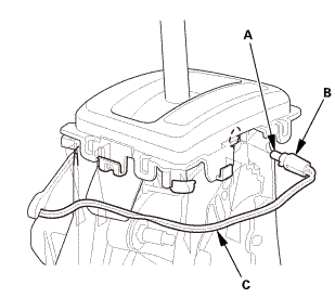
3.
|
Unhook the A/T gear position indicator panel light harness (C)
from the harness guides.
|
|
|
|
|
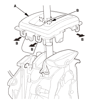
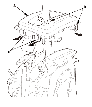
4.
|
Remove the A/T gear position indicator panel assembly (A) by
expanding the four lock tabs (B).
|
|
| 6. |
Shift Lock Release (Type B Shift Lever) |
|
|
|
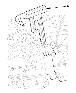
1.
|
Remove the shift lock release (A).
|
|
| 7. |
A/T Gear Position Indicator Panel Light Harness (Type B Shift Lever) |
|
|
|
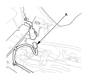
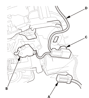
1.
|
Disconnect the connector (A).
|
|
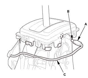
2.
|
Remove the park pin switch (B).
|
|
3.
|
Remove the connector clamp (C), then remove the A/T gear position
indicator panel light harness (D).
|
|

|
NOTE: Do not wipe off the special grease applied to the area of the shift
lever marked with an asterisk (*) when you assemble it.
|
| 1. |
A/T Gear Position Indicator Panel Light Harness (Type B Shift Lever) |
|
|
|
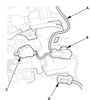
1.
|
Install the A/T gear position indicator panel light harness (A),
then install the connector clamp (B).
|
|
2.
|
Install the park pin switch (C).
|
|
3.
|
Connect the connector (D).
|
|
| 2. |
Shift Lock Release (Type B Shift Lever) |
|
|
|
1.
|
Install the shift lock release (A).
|
|
| 3. |
A/T Gear Position Indicator Panel Assembly (Type B Shift Lever) |
|
|
|
1.
|
Install the A/T gear position indicator panel assembly (A) by
aligning the four lock tabs (B).
|
|
|
|
|
2.
|
Install the A/T gear position indicator panel light bulb (A).
|
|
3.
|
Install the A/T gear position indicator panel light socket (B).
|
|
4.
|
Hook the A/T gear position indicator panel light harness (C)
to the harness guides.
|
|
| 4. |
Shift Lever Knob and Shift Lever Knob Ring |
|
1.
|
Install the shift lever knob (A) and the shift lever ring (B).
|
 mm
mm
|
|
|
2.
|
Pull down the shift lever ring (A) if necessary, and install
the shift lever knob ring (B).
|
|
3.
|
Pull up the shift lever ring to secure the knob ring.
|
|
| 5. |
Center Console Assembly |
|
|
|
1.
|
Install the center console (A), in the numbered sequence shown.
|
|
|
|
|
2.
|
Connect the connector (A).
|
|
|
|
|
3.
|
Install the bolts (A).
|
|
4.
|
Install the console box mat (B).
|
|
|
 mms.n mms.n
|
|
5.
|
Connect the connector (A).
|
|
6.
|
Install the bolts (B).
|
|
| 6. |
Cup Holder Panel Assembly |
|
|
|
1.
|
Install the cup holder panel assembly (A).
|
|
| 7. |
Center Console Panel Assembly (Except '12M M/T) |
|

|
|
1.
|
For some models: Connect the connector(s) (A).
|
|
2.
|
Install the center console panel (B).
|
|
|
|
|
3.
|
Install the clips (A).
|
|
NOTE: Do not wipe off the special grease applied to the area of the shift
lever marked with an asterisk (*) when you disassemble it.
1.
Shift Lever Knob and Sh ...
1.
Driver's Outer Vent
1.
Remove the driver's outer vent (A).
...
 A/T Gear Position Indicator Panel Assembly Removal and Installation (A/T, CVT)
 ECON Switch Removal and Installation ('13-'14)