Honda Civic Service Manual: Evaporator Expansion Valve Removal and Installation (Except Natural Gas models)
615130


|
||
|
||
|

|
NOTE: |
|
|||
|
| 1. | R-134a Refrigerant Recovery/Recycling/Charging Station - Connection |
|
|
|
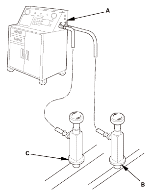
| 2. | A/C Refrigerant - Recovery |
|
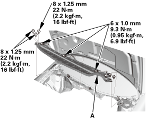
| 3. | Wiper Arm Assembly (K24Z7 engine) |
|
|
|
| 4. | Both Side Cowl Covers (K24Z7 engine) |
|
|
|
| 5. | Center Cowl Cover (K24Z7 engine) |
|
|
|

| 6. | Under-Cowl Panel (K24Z7 engine) |
|
|
|
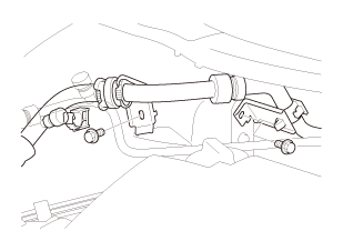
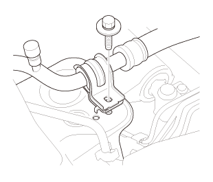
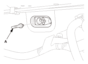
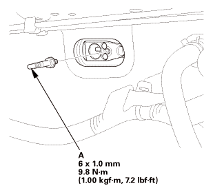
| 7. | A/C Line - Evaporator Side |
|
Except K24Z7 engine
|
|
|
K24Z7 engine
|
|
|
Flange bolt type
Stud bolt type
|
|
|
|
|
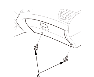
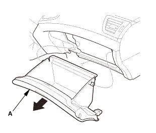
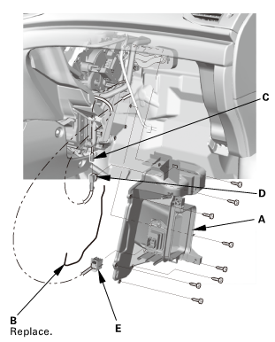
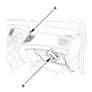
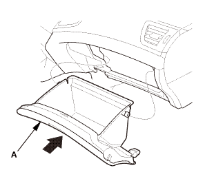
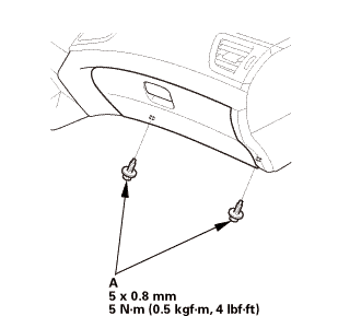
| 8. | Glove Box |
|
|
|
|
|
|
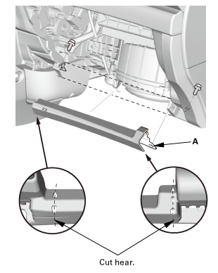
| 9. | Passenger's Heater Duct |
|
|
|
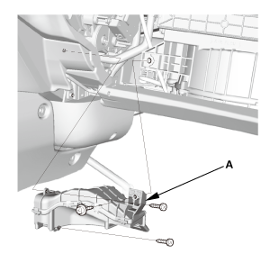
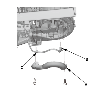
| 10. | Cross Brace |
|
|
|
|||||||||
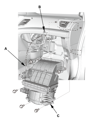
| 11. | Blower Motor Connector |
|
|
|
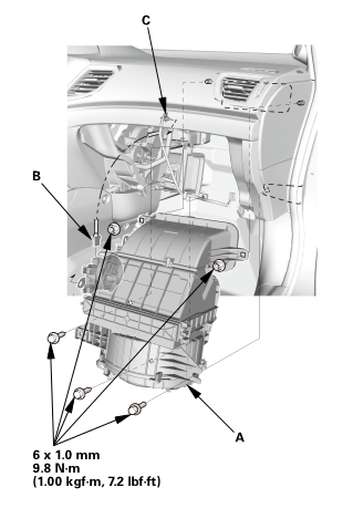
| 12. | Blower Unit |
|
|
|
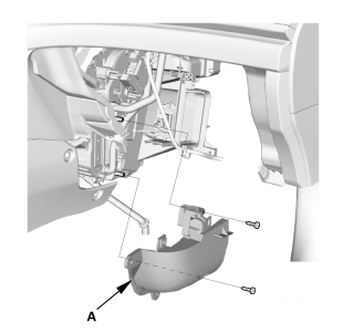
| 13. | Heater Core Cover |
|
|
|
| 14. | Expansion Valve Cover |
|
|
|
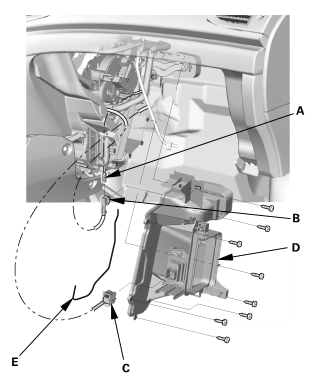
| 15. | Evaporator Assembly |
|
|
|

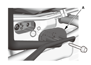
| 16. | Expansion Valve |
|
|
|

|
||
|
||
|
||
|
|
NOTE: |
|
|||
|
|||
|
|||
|
|||
|
|||
|
|||
|
|||
|
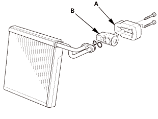
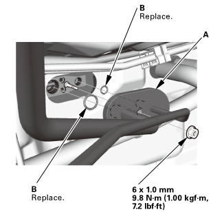
| 1. | Expansion Valve |
|
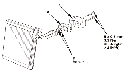
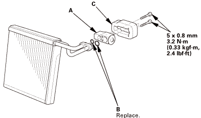
1. |
Install the expansion valve (A) with new O-rings (B) that are lubricated with clean refrigerant oil. |
2-door
4-door
 mm
mm
|
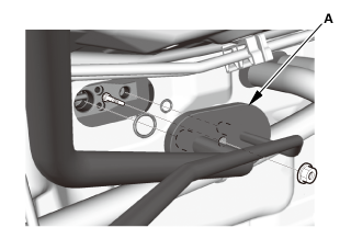
2. |
Install the insulator (C). |
| 2. | Evaporator Assembly |
|
|
|
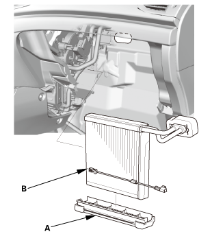
| 3. | Expansion Valve Cover |
|
|
|
| 4. | Heater Core Cover |
|
|
|
| 5. | Blower Unit |
|
|
|
| 6. | Blower Motor Connector |
|
|
|

| 7. | Passenger's Heater Duct |
|
|
|
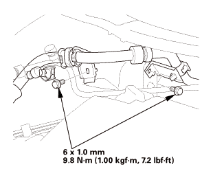
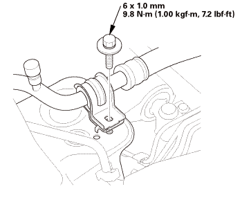
| 8. | A/C Line - Evaporator Side |
|
|
|
|
Stud bolt type
Flange bolt type
|
|
 mmmm
mmmm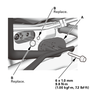
|
Except K24Z7 engine
|
|
 an
an|
K24Z7 engine
|
|
 u)mmn-in(mu
| 9. | Under-Cowl Panel (K24Z7 engine) |
|
|
|
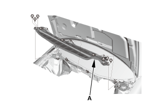
| 10. | Center Cowl Cover (K24Z7 engine) |
|
|
|
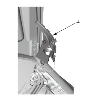
| 11. | Both Side Cowl Covers (K24Z7 engine) |
|
|
|
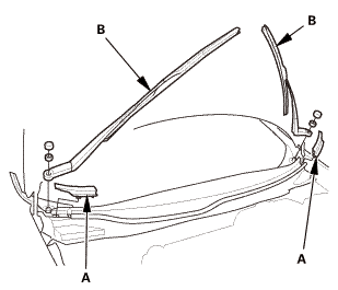
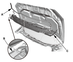
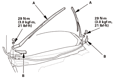
| 12. | Wiper Arm Assembly (K24Z7 engine) |
|
NOTE: Set the wiper arms to the auto-stop position before installation. |
|
1. |
Install the wiper arms (A). |
 25u....in
|
2. |
Install the cowl top wiper covers (B). |
| 13. | A/C System Evacuation |
|
| 14. | A/C Refrigerant - Charging |
|
1. |
Charge the system with the specified amount of R-134a refrigerant. Do not overcharge the system; the A/C compressor will be damaged. |
||||||||
|
Select the appropriate units of measure for your refrigerant charging station. |
|||||||||
|
|||||||||
| 15. | A/C Refrigerant - Leak Check |
|
Leak Detector Usage Tips (Refer to the Operator's Manual for complete operating instructions) |
|
|||
|
|||
|
|||
|
|||
|
|||
|
|||
|
|||
|
|||
|
Fluorescent Dye Usage Tips |
|
||||||||||||
|
||||||||||||
|
||||||||||||
|
||||||||||||
|
||||||||||||
|
|
1. |
With the engine OFF, use a halogen leak detector first to detect the leak source. Follow a continuous path in order to ensure that you will not miss any possible leaks. Test the following areas of the system for leaks: |
||||||||||||||||||||||||||||||||||||||||||||||||||||||||||||||||||||||||||
|
|||||||||||||||||||||||||||||||||||||||||||||||||||||||||||||||||||||||||||
|
2. |
Close the quick coupler valves, then disconnect the quick couplers from the vehicle service ports. |
|
3. |
Attach the universal connect set, from the Optimax Jr. Leak Detection Kit, to the service valve fitting. Close the control valve (the black knob on the connect set). |
|
4. |
Attach the charging station low pressure hose quick coupler to the service valve fitting, and open the quick coupler valve. Evacuate the connect set using the charging station vacuum pump, then close the quick coupler valve. |
|
5. |
Detach the universal connect set, and install a Tracer-Stick® dye capsule between the connect set and the service valve fitting (see the manufacturer's instructions for more detail). |
|
6. |
Attach the quick coupler on the universal connect set to the low pressure service port on the vehicle. Open the charging station low pressure hose quick coupler valve, but do not open the control valve. |
|
7. |
Start the engine, and set the A/C system to maximum cooling. Open the control valve to let refrigerant and the dye enter the A/C system through the low pressure service port. Close the control valve when the Tracer-Stick® dye capsule is empty. |
|
8. |
Run the engine and A/C system for 15 minutes to thoroughly circulate the dye. Then shut the engine off, and inspect the following areas of the system for leaks: |
|||||||||||||||||||||||||||||||||||||||||||||||||||||||||||||||||||||||||||||||
|
NOTE: |
||||||||||||||||||||||||||||||||||||||||||||||||||||||||||||||||||||||||||||||||
|
||||||||||||||||||||||||||||||||||||||||||||||||||||||||||||||||||||||||||||||||
|
||||||||||||||||||||||||||||||||||||||||||||||||||||||||||||||||||||||||||||||||
| 16. | A/C System - Test |
|
|
|
||||||||||||||||||||||||||||||||||||||||||||||||||||||||||||||||||||||||
|
6. |
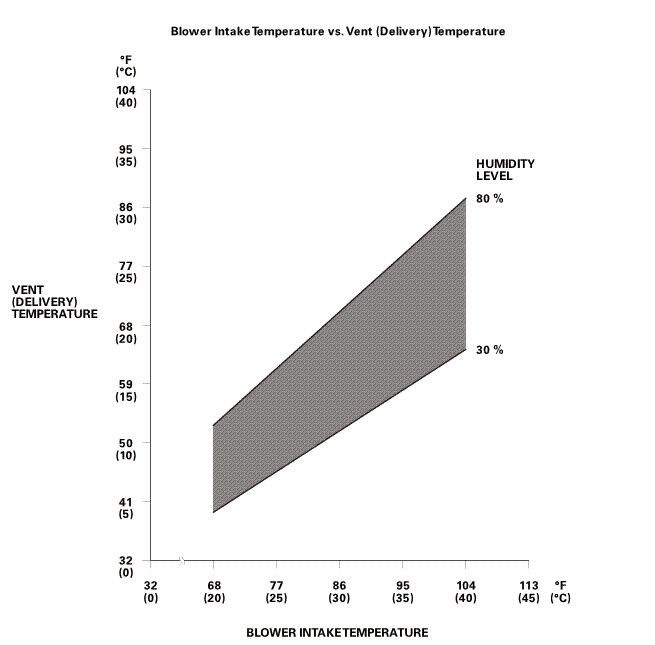
To complete the vent (delivery)/blower intake temperature chart: |
|||||||||||||||||
|
||||||||||||||||||
|
NOTE: The vent (delivery) temperature and blower intake temperature should intersect in the shaded area. Any measurements outside the line may indicate the need for further inspection. |
||||||||||||||||||
 orhuullnrrvlevel11vmrsono):277-rin)ian)amwinintaketemperature
|
7. |
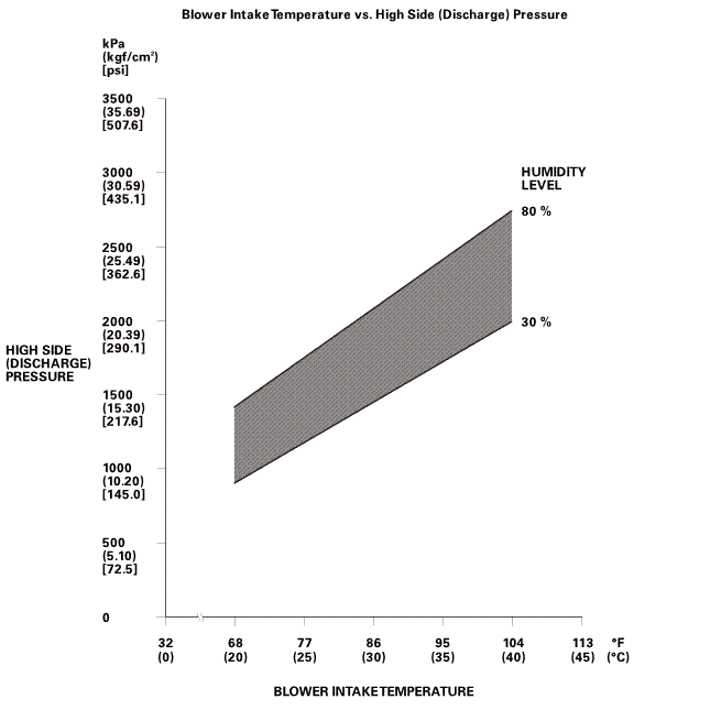
To complete the high side (discharge) pressure/blower intake temperature chart: |
|||||||||||||||||
|
||||||||||||||||||
|
NOTE: The high side (discharge) pressure and blower intake temperature should intersect in the shaded area. Any measurements outside the line may indicate the need for further inspection. |
||||||||||||||||||
 sun:highnuwuomlevel2217-s
|
8. |
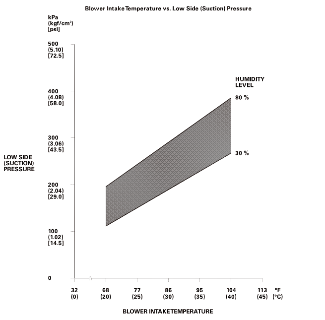
To complete the low side (suction) pressure/blower intake temperature chart: |
|||||||||||||||||
|
||||||||||||||||||
|
NOTE: The low side (suction) pressure and blower intake temperature should intersect in the shaded area. Any measurements outside the line may indicate the need for further inspection. |
||||||||||||||||||
 turn(suction)snnhuuunrrvlevel(sucnomzoo(am[am77-r(ulam
| 17. | Cross Brace |
|
|
|
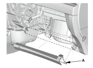
| 18. | Glove Box |
|
|
|
|
|
|
 Evaporator Core Removal and Installation (Natural Gas models)
Air conditioning refrigerant or lubricant vapor can irritate
your eyes, nose, or throat.
...
 Evaporator Expansion Valve Removal and Installation (Except Natural Gas models)
615130
Air conditioning refrigerant or lubricant vapor can irritate
your eyes, nose, or throat.
...
See also:
Honda Civic Service Manual. Center Console Beverage Holder Removal and Installation
044100
Removal
1.
M/T Shift Lever Knob
Except K24Z7 engine
1.
Except K24Z7 engine: Lower the shift lever boot (A) to release
the hooks from the boot.
...
