|
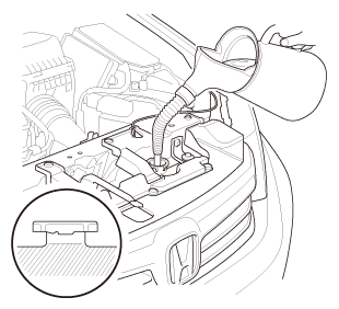
1.
|
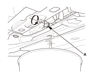
Follow the chart and pour coolant into the radiator up to the base of
the filler neck.
|
|
NOTE:
|
|

|
Use Honda Long Life Antifreeze/Coolant Type 2, and if
necessary add Honda Extreme Cold Weather Antifreeze/Coolant
Type 2 (concentrate). Using a non-Honda coolant can result
in corrosion, causing the cooling system to malfunction
or fail.
|
|
|
|
Honda Long Life Antifreeze/Coolant Type 2 is a mixture
of 50 % antifreeze and 50 % water. Honda Extreme Cold Weather
Antifreeze/Coolant Type 2 is a 100 % concentration coolant.
Do not add water to either coolant.
|
|
|
|
If the vehicle is regularly driven in very low temperatures
(below -22 °F ( -30 °C)), a 60 % concentration of coolant
should be used.
|
|
|
|
|
Operation
|
Vehicle Usage (Desired Mixture)
|
Current Mixture
|
Coolant Drain
|
Add Amount of Honda Extreme Cold Weather Antifreeze/Coolant
Type 2 (100 % concentrate)
|
Then add Honda Long Life Antifreeze/Coolant Type 2 (50/50)
|
|
Coolant Change
|
Normal Area (50/50)
|
50/50
60/40
unknown
|
Drain radiator, engine block, and reservoir
|
None
|
Top off the cooling system
|
|
Very Cold Area (60/40)
|
50/50
unknown
|
Drain radiator, engine block, and reservoir
|
About 1.3 L (44 fl oz)
|
|
60/40
|
About 1.2 L (41 fl oz)
|
|
Engine Overhaul
|
Normal Area (50/50)
|
-
|
-
|
None
|
|
Very Cold Area (60/40)
|
-
|
-
|
About 1.2 L (41 fl oz)
|
|
Coolant Winterizing
|
Very Cold Area (60/40)
|
50/50
|
Drain about 2.0 L (68 fl oz) from radiator
|
About 1.2 L (41 fl oz)
|
|
unknown*
|
Drain radiator, engine block, and reservoir
|
|
|
|
|
*: When you want to winterize the coolant with the minimum amount of
coolant change but the current coolant concentration in the vehicle is unknown,
you must drain all coolant from the cooling system.
|
|
|
Engine Coolant Capacities (Including the coolant reservoir
capacity of 0.475 L (0.1255 US gal))
|
|
|
|
|
|
Except K24Z7 engine
|
| |
Manufacturer
|
Capacity
|
|
At Coolant Change
|
DENSO
|
5.59 L (1.477 US gal)
|
|
TRAD
|
5.50 L (1.453 US gal)
|
|
After Engine Overhaul (M/T)
|
DENSO
|
6.42 L (1.696 US gal)
|
|
TRAD
|
6.33 L (1.672 US gal)
|
|
After Engine Overhaul (A/T)
|
DENSO
|
6.56 L (1.732 US gal)
|
|
TRAD
|
6.47 L (1.709 US gal)
|
|
After Engine Overhaul (CVT)
|
DENSO
|
6.52 L (1.722 US gal)
|
|
TRAD
|
6.43 L (1.699 US gal)
|
|
|
|
|
|
Engine Coolant Capacities (Including the coolant reservoir
capacity of 0.475 L (0.1255 US gal))
|
|
|
|
|
|
K24Z7 engine
|
| |
Capacity
|
|
At Coolant Change
|
5.5 L (1.45 US gal)
|
|
After Engine Overhaul
|
6.7 L (1.78 US gal)
|
|
|
|
See also:
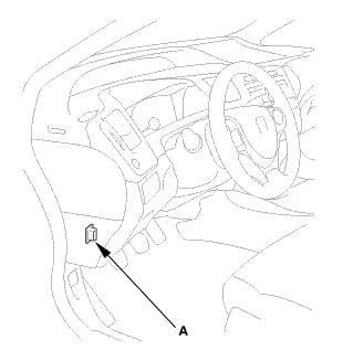
Honda Civic Owners Manual. VSA On and Off
This button is on the driver side control panel.
To partially disable VSA functionality/
features, press and hold it until you hear a
beep.
The traction control stops fully functioning,
allowing the wheels to spin more freely at low
speed. The VSA OFF indicator will also come
on and a ...


 vnm
vnm

 125mmmmmm
 u.amm
u.amm .2slam,is

 vnm
vnm
 isum
isum

 Coolant Replacement (R18A9)
 Thermostat