Honda Civic Service Manual: Valve Stem-to-Guide Clearance Inspection (K24Z7)

| 1. | Vehicle Lift |
|
| 2. | Splash Shield |
|
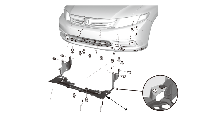
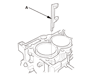
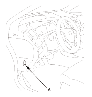
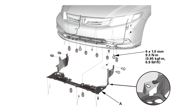
1. |
Remove the splash shield (A). |
| 3. | Radiator Cap |
|
| 4. | Radiator Coolant - Replacement |
|
|
|
| 5. | Fuel Filler Cap |
|
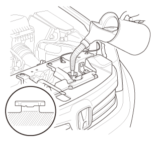
| 6. | HDS DLC - Connection |
|
|
|

| 7. | Fuel Pump Off |
|
||||||||||||||||||||||||

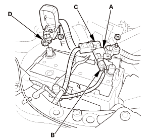
| 8. | Battery Terminal - Disconnection |
|
|
|
|||||||||||||||||||||||||||
| 9. | Fuel Pressure - Relieving |
|
|
|
|
|
|
|
|
|
|
|
|
|||||||||||||||||||||||||
| 10. | Air Cleaner Assembly |
|
|
|
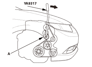
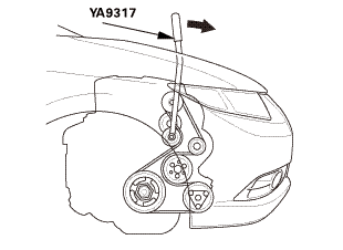
| 11. | Drive Belt |
|
|
|
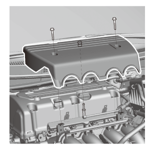
 vnm
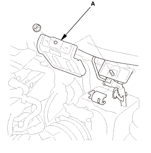
vnm| 12. | Engine Cover |
|
|
|
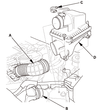
| 13. | Intake Air Duct |
|
|
|
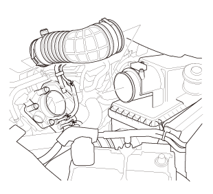
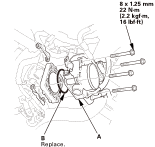
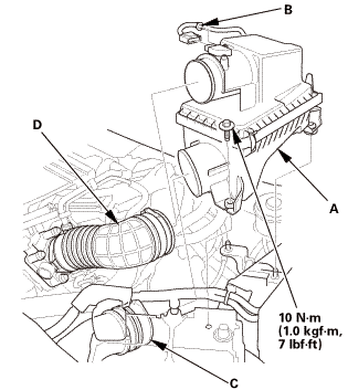
| 14. | Throttle Body - Removal |
|
|
|
|
|
|
|
|
|
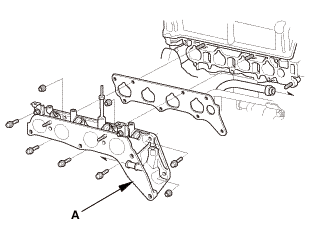
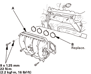
| 15. | Intake Manifold Assembly |
|
|
|
|
|
|
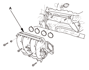
|
|
|
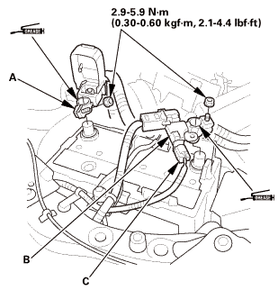
| 16. | Ignition Coil Harness - Move |
|
|
|
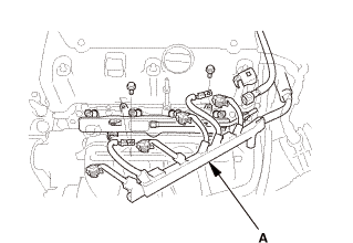
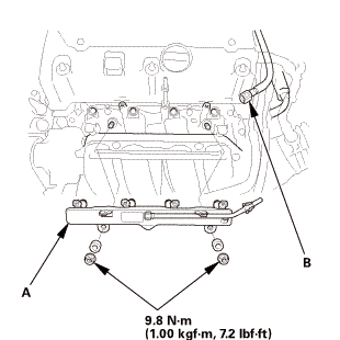
| 17. | Fuel Injector and Rail Assembly |
|
|
|
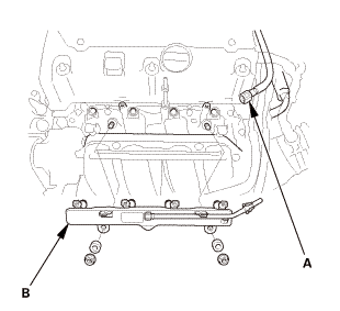
| 18. | Injector Base Assembly |
|
|
|
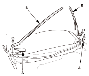
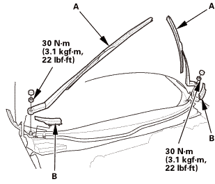
| 19. | Wiper Arm Assembly |
|
|
|
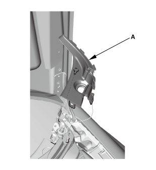
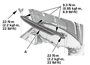
| 20. | Both Side Cowl Covers |
|
|
|
| 21. | Center Cowl Cover |
|
|
|
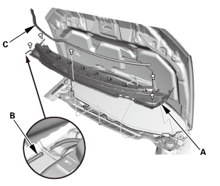
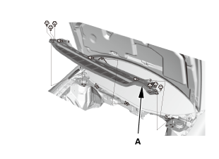
| 22. | Under Cowl Panel |
|
|
|
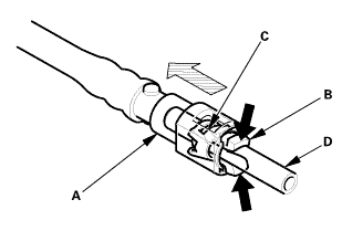
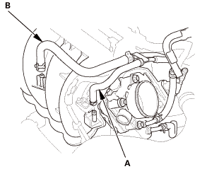
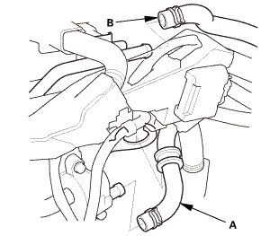
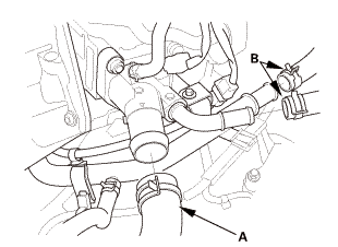
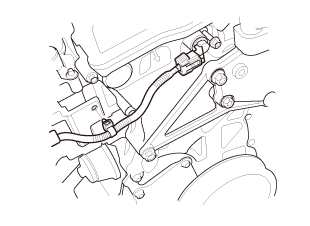
| 23. | Engine Peripheral Hose - Disconnection |
|
|
|
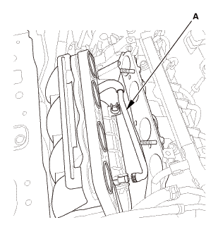
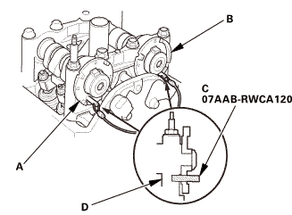
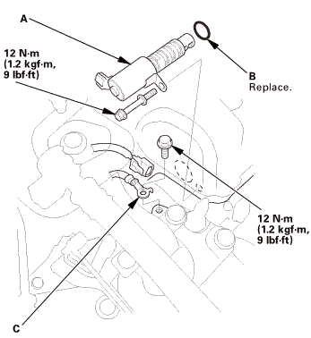
| 24. | Rocker Arm Oil Control Valve |
|
|
|
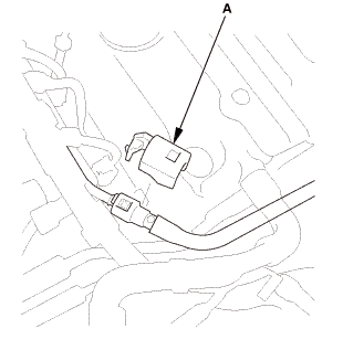
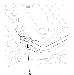
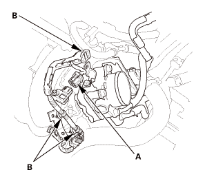
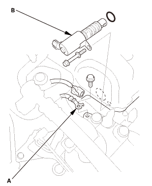
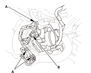
| 25. | A/F Sensor |
|
|
|
| 26. | WU-TWC |
|
|
|
| 27. | Heater Hose - Disconnection Engine Side |
|
|
|
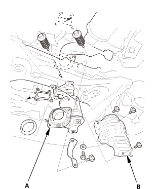
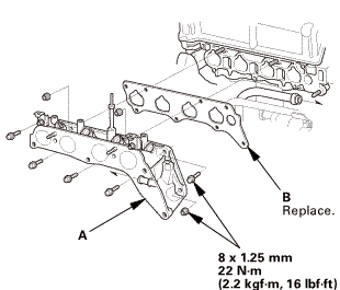
| 28. | Cylinder Head Peripheral Assembly |
|
|
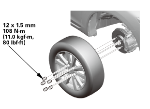
|
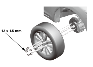
| 29. | Tire and Wheel-Removal, Front Right |
|
|
|
 12x1mm
| 30. | Ignition Coil Cover |
|
|
|
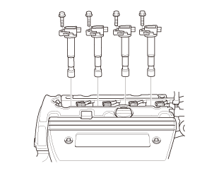
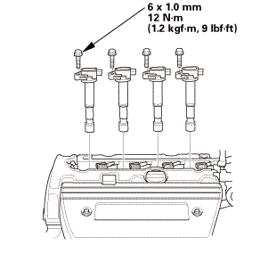
| 31. | Ignition Coil |
|
|
|
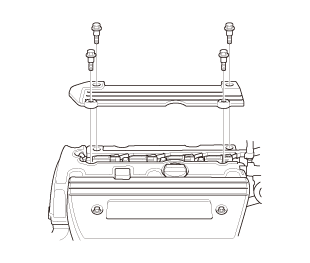
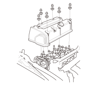
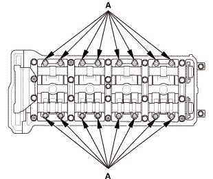
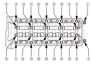
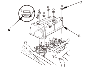
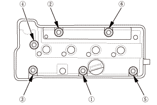
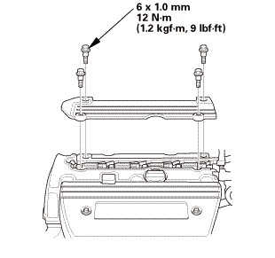
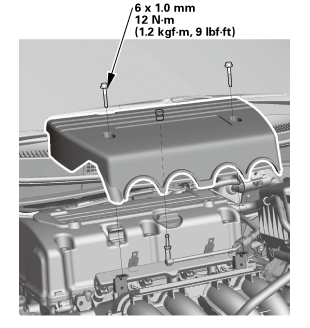
| 32. | Cylinder Head Cover |
|
|
|
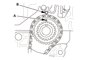
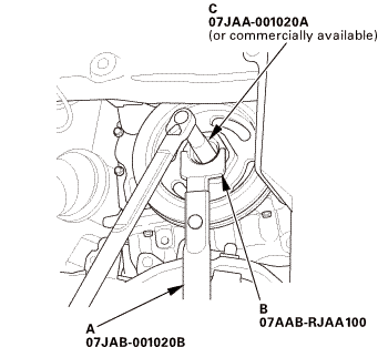
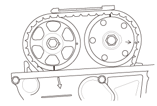
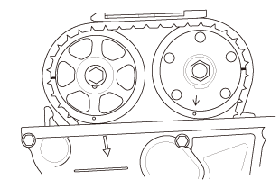
| 33. | Set The Crankshaft To Top Dead Center |
|
|
|
||||||
| 34. | Cam Chain Case Peripheral Assembly |
|
|
|
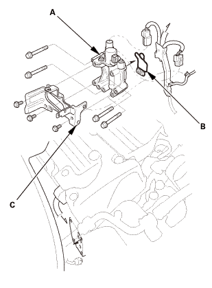
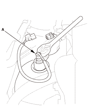
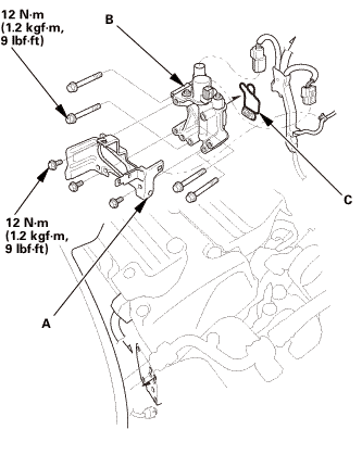
| 35. | VTC Oil Control Solenoid Valve |
|
|
|
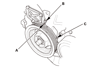
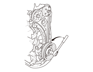
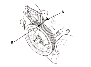
| 36. | Crankshaft Pulley |
|
|
|
 1aah(jaal0a
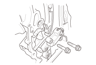
| 37. | Engine Jack Support (State Of A Low Vehicle) |
|
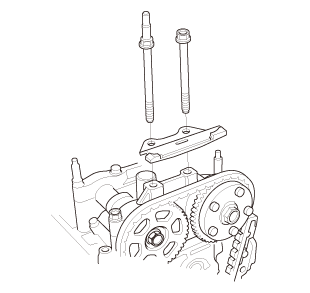
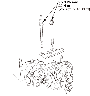
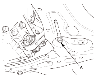
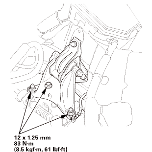
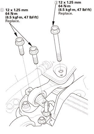
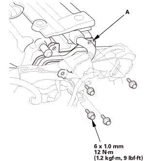
| 38. | Upper Torque Rod |
|
|
|
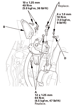
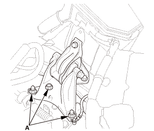
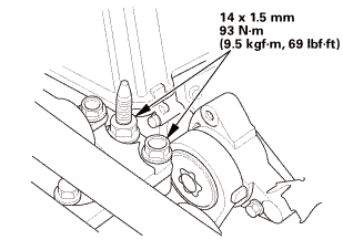
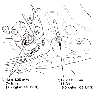
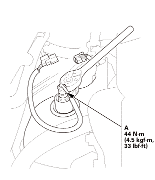
| 39. | Side Engine Mount |
|
|
|
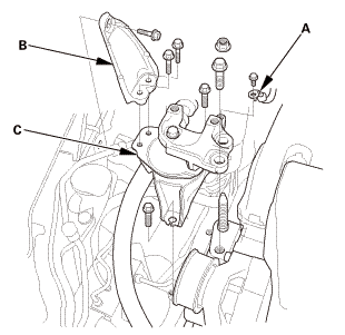
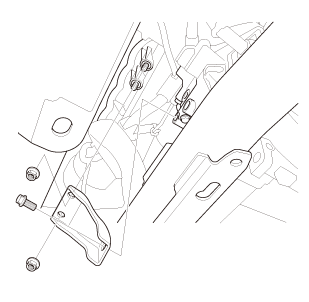
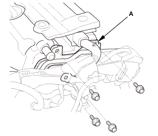
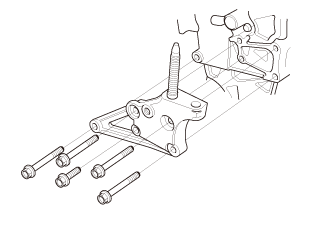
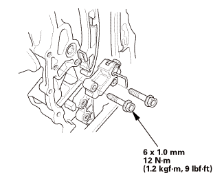
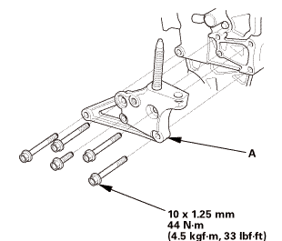
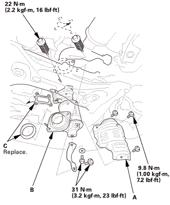
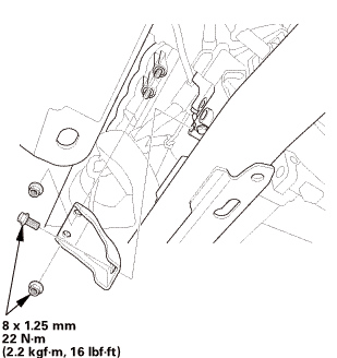
| 40. | Side Engine Mount Bracket, Engine Side |
|
|
|
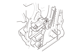
| 41. | Cam Chain Case |
|
|
|
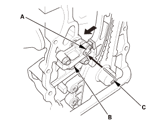
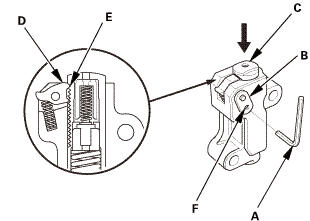
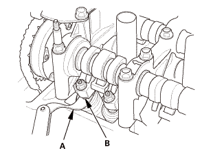
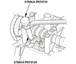
| 42. | Cam Chain Auto-Tensioner |
|
|
|
|
|
|
||||||
|
|
|
| 43. | Cam Chain Tensioner Arm and Cam Chain Guide |
|
|
|
|
|
|
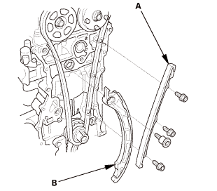
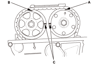
| 44. | Cam Chain |
|
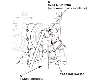
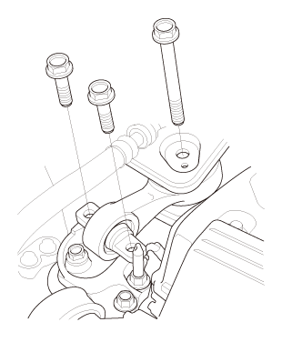
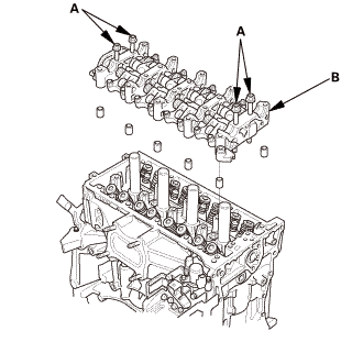
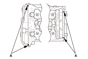
| 45. | Camshaft Holder |
|
|
|
|
|
|
|
|
|
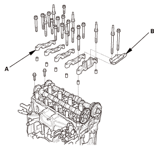
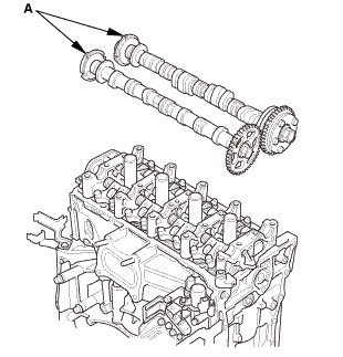
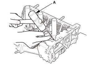
| 46. | Camshaft |
|
|
|
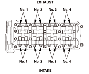
| 47. | Rocker Arm Assembly |
|
|
|
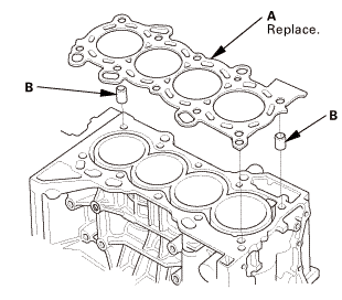
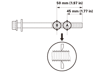
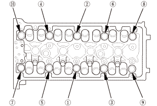
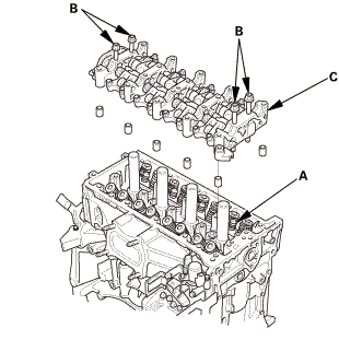
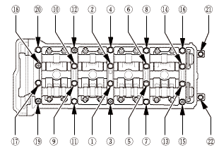
| 48. | Cylinder Head Assembly |
|
|
|
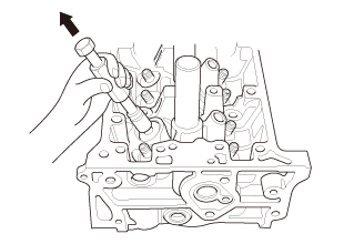
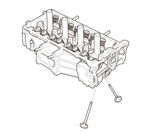
| 49. | Valve and Valve Spring |
|
|
|
|
|
|
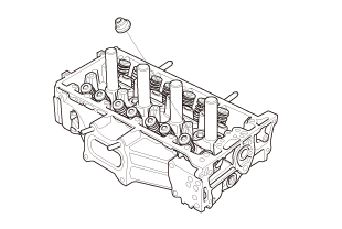
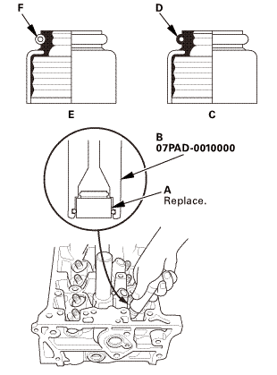
| 50. | Valve Seal and Valve Spring Seat |
|
|
|
|
|
|
|
|
|

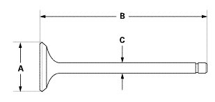
| 1. | Valve - Inspection |
|
1. |
Measure the valve in these areas. |
|||||||||||||
|
||||||||||||||
|
||||||||||||||
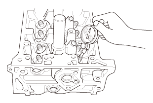
| 2. | Valve Stem To Guide Clearance - Inspection |
|
1. |
Subtract the O.D. of the valve stem, measured with a micrometer, from the I.D. of the valve guide, measured with an inside micrometer or a ball gauge. Take the measurements in three places along the valve stem and three places inside the valve guide. The difference between the largest guide measurement and the smallest stem measurement should not exceed the service limit. |
|||||||||
|
||||||||||
|
||||||||||

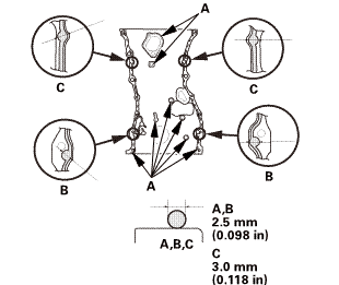
| 1. | Valve Seal and Valve Spring Seat |
|
|
|
|
|
|
|
|
|
|||||||||
| 2. | Valve and Valve Spring |
|
|
|
|
|
|
||||||
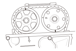
| 3. | Set The Crankshaft To Top Dead Center |
|
|
|
| 4. | Cylinder Head Assembly |
|
|
|
|
|
|
|
|
|
|
|
|
|
|
|
||||||
 szconn
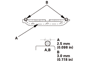
| 5. | Rocker Arm Assembly |
|
|
|
||||||||||||||||||||
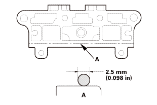 2.5mm
2.5mm|
|
|
||||||||||||
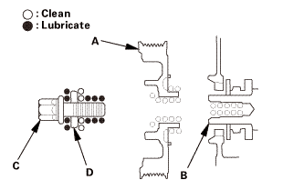
| 6. | Camshaft |
|
|
|
| 7. | Camshaft Holder |
|
|
|
|
|
|
||||||||||||
 ,
,

| 8. | Cam Chain |
|
|
|
|
|
|
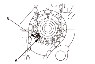
|
|
|
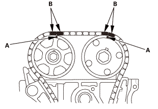
| 9. | Cam Chain Tensioner Arm and Cam Chain Guide |
|
|
|
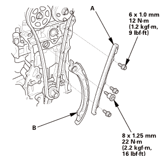
|
|
|
 (21m,mm
| 10. | Cam Chain Auto-Tensioner |
|
|
|
||||||
|
|
|
|
|
|
|
|
|
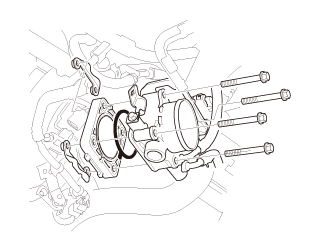
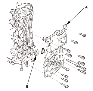
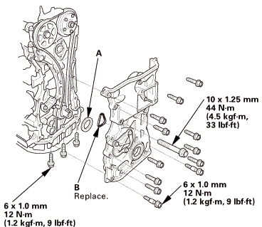
| 11. | Cam Chain Case |
|
|
|
|||||||||||||||||||||||||||
|
|
|
|||||||||||||||||||||
 .min)
.min)|
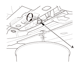
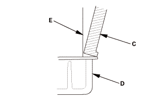
6. |
Install the spacer (A), then install a new O-ring (B) on the chain case. Set the edge of the chain case (C) to the edge of the oil pan (D), then install the chain case on the engine block (E). Wipe off the excess liquid gasket on the oil pan and the chain case mating area. |
|||||||||||||
|
NOTE: |
||||||||||||||
|
||||||||||||||
 tommi2mmu....
| 12. | Side Engine Mount Bracket, Engine Side |
|
|
|
| 13. | Side Engine Mount |
|
|
|
 replace.(s.nm,
| 14. | Transmission Mount - Loosen |
|
|
|
| 15. | Lower Torque Rod Mounting Bolt - Loosen |
|
|
|
| 16. | Side Engine Mount - Tighten |
|
|
|
 -.smmn-m
| 17. | Transmission Mount - Tighten |
|
|
|
 :2mmn-m
| 18. | Lower Torque Rod Mounting Bolt - Tighten |
|
|
|
| 19. | Upper Torque Rod |
|
|
|
 mmreplace.mm
| 20. | Crankshaft Pulley |
|
|
|
|
|
|
 1aah(jaal0a
| 21. | VTC Oil Control Solenoid Valve |
|
|
|
||||||||||||||||||||
| 22. | Cam Chain Case Peripheral Assembly |
|
|
|
| 23. | Valve Clearance - Adjustment |
|
|
|
|
2. |
Select the correct feeler gauge for the valve clearance you are going to check. |
|||||||||
|
||||||||||
|
|
|
|
|
|
|||||||||||||||
|
|
|
|
|
|
|
|
|
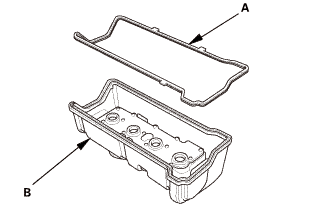
| 24. | Cylinder Head Cover |
|
|
|
||||||||||||
|
|
|
||||||||||||
|
|
|
|
|
|
|||||||||||||||||
| 25. | Ignition Coil |
|
|
|
| 26. | Ignition Coil Cover |
|
|
|
| 27. | Cylinder Head Peripheral Assembly |
|
|
|
 sxmmmn-nl
| 28. | Heater Hose - Reconnection Engine Side |
|
|
|
| 29. | WU-TWC |
|
|
|
 22am...(3
| 30. | A/F Sensor |
|
|
|
| 31. | Rocker Arm Oil Control Valve |
|
|
|
| 32. | Engine Peripheral Hose - Reconnection |
|
|
|
| 33. | Under Cowl Panel |
|
|
|
 22mm)2222
| 34. | Center Cowl Cover |
|
|
|

| 35. | Both Side Cowl Covers |
|
|
|
| 36. | Wiper Arm Assembly |
|
|
|
 1.122
1.122| 37. | Injector Base Assembly |
|
|
|
| 38. | Fuel Injector and Rail Assembly |
|
|
|
| 39. | Ignition Coil Harness - Move |
|
|
|
| 40. | Intake Manifold Assembly |
|
|
|
|
|
|
|
|
|
 isum
isum| 41. | Throttle Body - Installation |
|
|
|
|
|
|
|
|
|
| 42. | Intake Air Duct |
|
|
|
| 43. | Drive Belt |
|
|
|
 vnm
vnm| 44. | Air Cleaner Assembly |
|
|
|
| 45. | Tubes, Hoses, and Connectors After Installation Check |
|
| 46. | Fuel Filler Cap |
|
| 47. | Battery Terminal - Reconnection |
|
|
|
|||||||||||||||||||
| 48. | HDS DLC - Connection |
|
|
|
| 49. | Fuel Pump On |
|
||||||||||
| 50. | Fuel Line Leak Check |
|
| 51. | Radiator Coolant - Replacement |
|
1. |
Follow the chart and pour coolant into the radiator up to the base of the filler neck. |
|||||||||||||||||||||||||||||||||||||
|
NOTE: |
||||||||||||||||||||||||||||||||||||||
|
||||||||||||||||||||||||||||||||||||||
|
||||||||||||||||||||||||||||||||||||||
|
*: When you want to winterize the coolant with the minimum amount of coolant change but the current coolant concentration in the vehicle is unknown, you must drain all coolant from the cooling system. |
||||||||||||||||||||||||||||||||||||||
|
||||||||||||||||||||||||||||||||||||||
|
||||||||||||||||||||||||||||||||||||||
|
||||||||||||||||||||||||||||||||||||||
|
||||||||||||||||||||||||||||||||||||||
| 52. | Engine Cover |
|
|
|
| 53. | Tire and Wheel-Installation, Front Right |
|
|
|
||||||
 mminmuan
| 54. | Splash Shield |
|
1. |
Install the splash shield (A). |
| 55. | Warm Up The Engine |
|
| 56. | Idle Speed - Inspection |
|
||||||||||||||||||||||
| 57. | CKP Pattern Clear/CKP Pattern Learn |
|
| 58. | Ignition Timing - Inspection |
|
|
|
|
|
|
||||||||||||||||
| 59. | Maintenance Minder Reset |
|
 Tire Sealant Removal
NOTE:
This procedure is only to be used with the temporary tire repair
kit.
...
 Valve Stem-to-Guide Clearance Inspection (R18A9)
1.
Fuel Pressure - Relieving (Between the engine and the manual shut-off
valve) (Natural Gas Model)
Compressed natural gas is flammable and h ...
See also:
Honda Civic Owners Manual. Using the Trunk Release Button
Models with smart entry system
Push up the release button on the trunk lid
after the doors are unlocked.
When You Cannot Open the Trunk
Even if the trunk is locked, you can open the
trunk if you carry the smart entry remote.
Some exterior lights flash and the beeper
sounds.
Using t ...
