Honda Civic Service Manual: Synchro Ring and Gear Inspection (K24Z7)

Removal
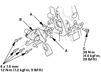
| 1. | M/T Change Lever Assembly |
|
|
|
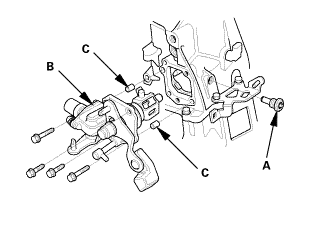
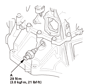
| 2. | Back-Up Light Switch |
|
|
|
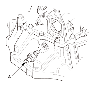
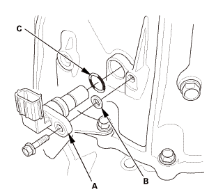
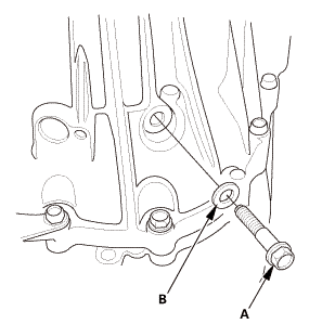
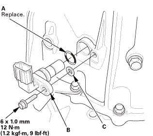
| 3. | Output Shaft (Countershaft) Speed Sensor |
|
|
|
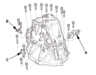
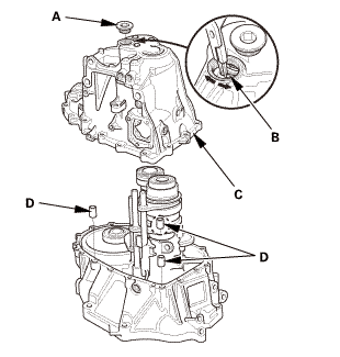
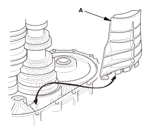
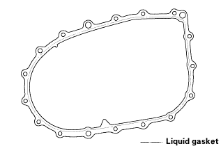
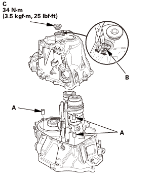
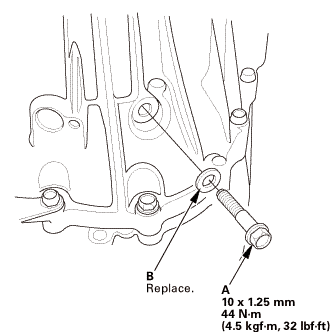
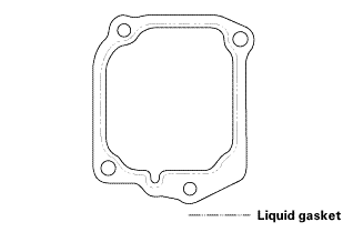
| 4. | Transmission Housing |
|
|
|
|
|
|
|
|
|
|
|
|
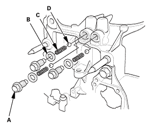
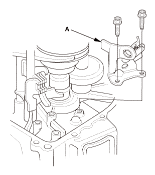
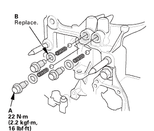
| 5. | Reverse Shift Fork |
|
|
|
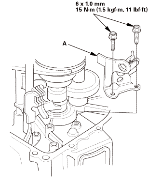
| 6. | Baffle Plate |
|
|
|
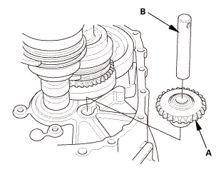
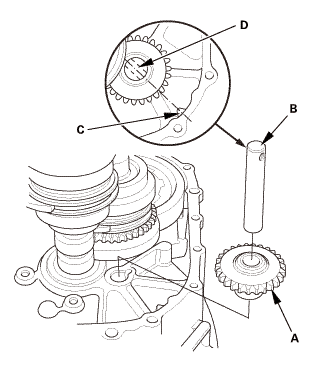
| 7. | Reverse Idler Gear |
|
|
|
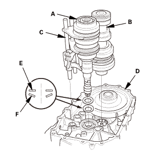
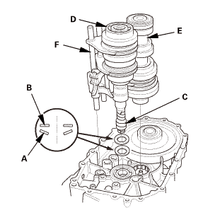
| 8. | M/T Mainshaft and Countershaft and Shift Fork Assembly |
|
|
|
|||||||||||||||
| 9. | M/T Mainshaft 5th and 6th Gear |
|
|
|
|
|
|
|||||||||
| 10. | M/T Mainshaft 3rd and 4th Gear |
|
|
|
|||||||||
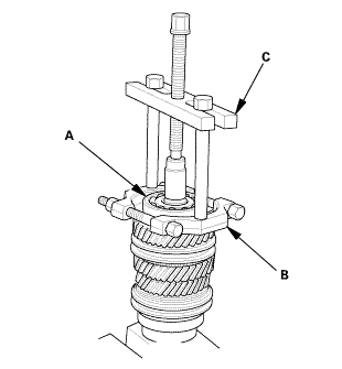
| 11. | M/T Countershaft |
|
|
|
|
|
|
|
|
|
|
|
|
 Inspection
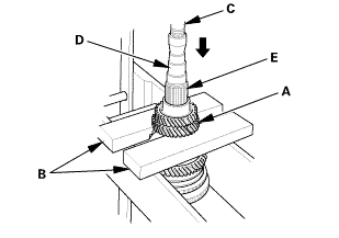
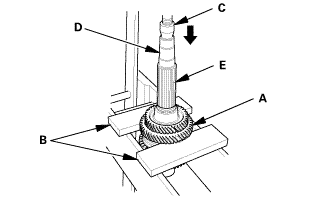
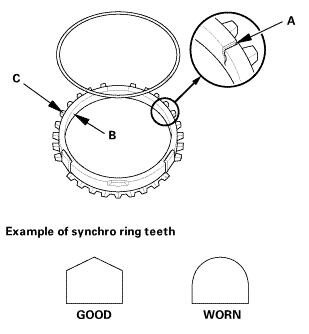
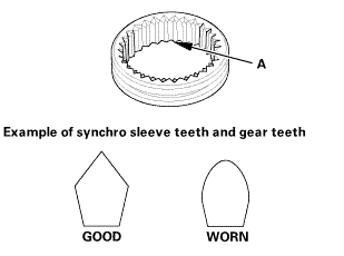
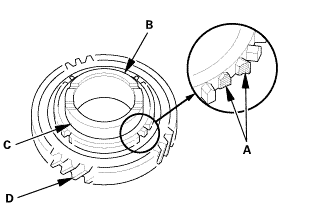
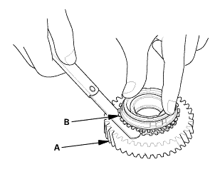
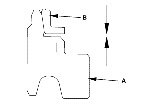
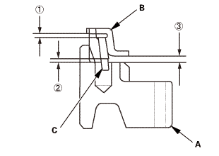
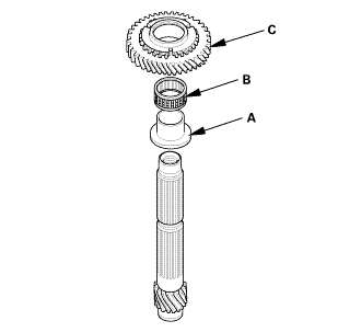
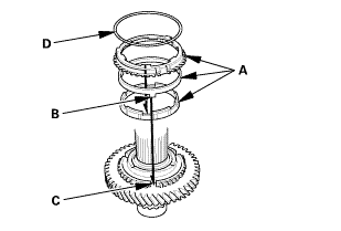
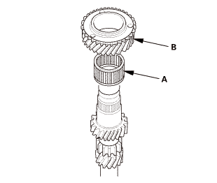
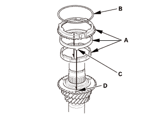
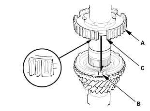
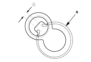
| 1. | Synchro Ring and Gear Inspection |
|
|
|
|
|
|
 sleeveandworm
|
|
|
||||||||||||||||||
|
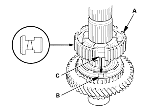
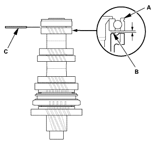
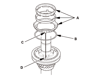
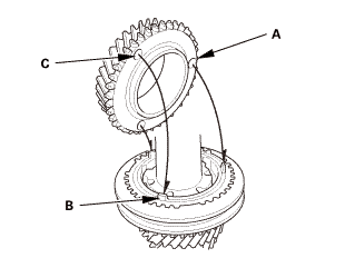
Synchro ring-to-gear
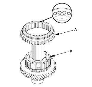
Double cone synchro and triple cone synchro-to-gear
|
|
|||||||||||||||||||||||||||||||||||||||||||||||||||||||||||||||||||||||||||||||||||
 :
: :
: :
:
Installation
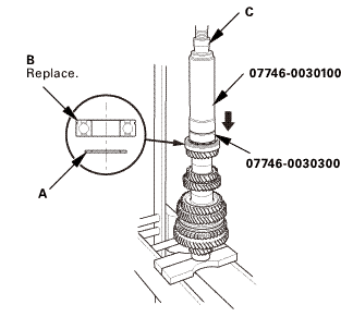
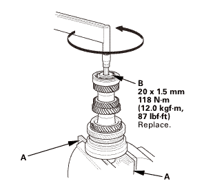
| 1. | M/T Countershaft |
|
|
|
|
|
|
|
|
|
|
|
|
|||||||||
|
|
|
|
|
|
|
|
|
|
|
|
|||||||||
 sun
sun|
|
|
||||||
 s,m
s,m|
|
|
||||||
 (2,snn
|
|
|
||||||
 zs,4ioums.uuau1uu
|
|
|
||||||||||||||||||||
 nms.nn:mnn
|
|
|
||||||||||||||||||||||||||||||||||||||||||||||||||||||||||||||||||||||||||||||
|
|
|
|
|
|
||||||
|
|
|
|||||||||||||||
 nms.nu:n1nn
|
|
|
|||||||||
 mm(noumn
| 2. | M/T Mainshaft 3rd and 4th Gear |
|
|
|
|
|
|
|
|
|
||||||
|
|
|
|
|
|
|
|
|
|
|
|
| 3. | M/T Mainshaft 5th and 6th Gear |
|
|
|
|
|
|
|
|
|
|
|
|
|||||||||
|
|
|
|
|
|
| 4. | M/T Mainshaft and Countershaft and Shift Fork Assembly |
|
|
|
||||||||||||||||||
| 5. | Reverse Idler Gear |
|
|
|
| 6. | Baffle Plate |
|
|
|
| 7. | Reverse Shift Fork |
|
|
|
 mmlbf!
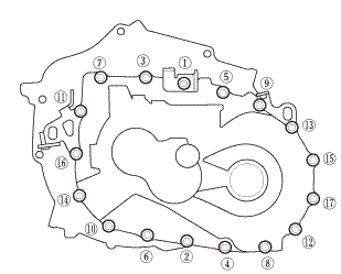
| 8. | Transmission Housing |
|
|
|
||||||||||||||||||||
|
|
|
|||||||||||||||
|
|
|
|||||||||||||||||||||||
|
|
|
|
|
|
||||||||||
|
|
|
|
|
|
| 9. | Output Shaft (Countershaft) Speed Sensor |
|
|
|
| 10. | Back-Up Light Switch |
|
|
|
| 11. | M/T Change Lever Assembly |
|
|
|
||||||||||||||||||||
 iukn
iukn|
|
|
 M/T Shift Fork Disassembly and Reassembly (R18Z1 M/T)
View
NOTE: Prior to reassembling, clean all parts in solvent, dry them, and
apply MTF to any contact surfaces.
1.
M/T Shift Fork Exploded View
...
 Synchro Ring and Gear Inspection (R18Z1 M/T)
Removal
1.
M/T Change Lever Assembly
1.
Remove the change lever assembly (A).
...
See also:
Honda Civic Service Manual. Front Fog Light Bulb Removal and Installation ('13-'14: 4-door)
1.
Front Fog Light Trim
Except Si model
Si model
1.
Remove the front fog light trim (A).
...
