Honda Civic Service Manual: Receiver/Dryer Desiccant Removal and Installation ('13)

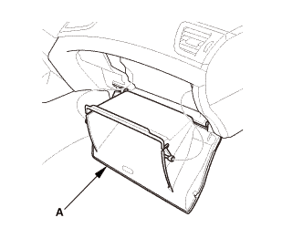
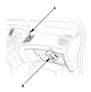
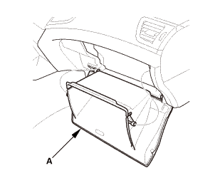
| 1. | Glove Box - Move |
|
|
|
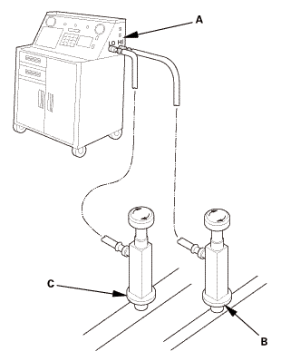
| 2. | R-134a Refrigerant Recovery/Recycling/Charging Station - Connection |
|
|
|
| 3. | A/C Refrigerant - Recovery |
|
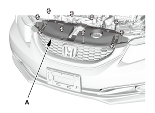
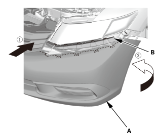
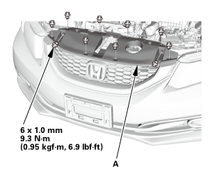
| 4. | Front Grille Cover |
|
|
|
|
|
|
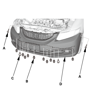
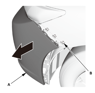
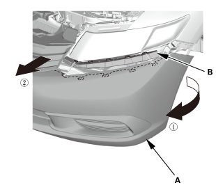
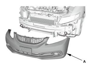
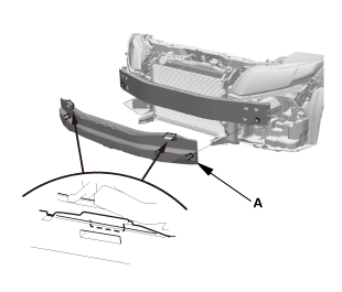
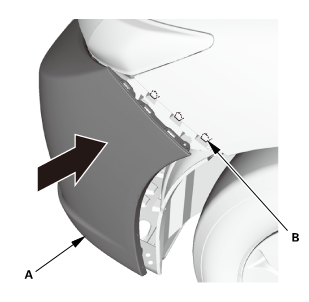
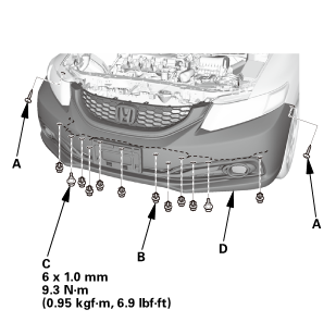
| 5. | Front Bumper |
|
|
|
|
|
|
|
|
|
|
|
|
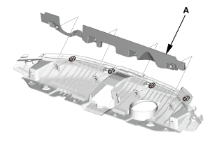
| 6. | Front Bumper Absorber |
|
|
|
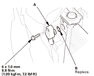
| 7. | A/C Line - Disconnection (A/C Condenser Side) |
|
|
|
|
|
|
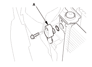
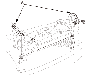
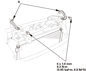
| 8. | Both A/C Condenser Upper Mount Bracket |
|
|
|
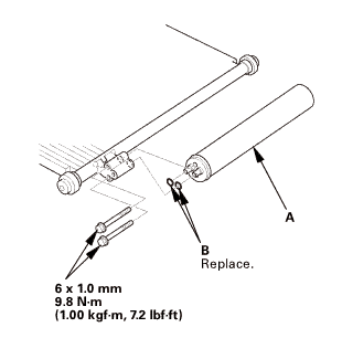
| 9. | A/C Condenser Assembly |
|
|
|
||||||
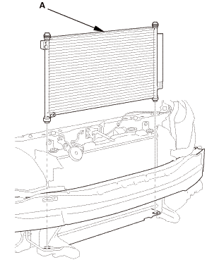
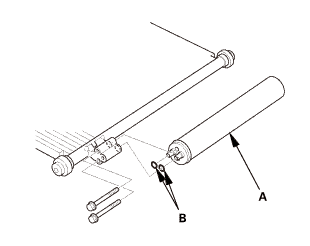
| 10. | Receiver/Dryer Desiccant |
|
|
|
|
|
|

| 1. | A/C Refrigerant Oil - Replacement |
|
Recommended PAG oil: SP-10 |
|
P/N 38897-P13-A01AH: 120 mL (4 fl·oz) |
|
It is important to have the correct amount of refrigerant oil in the A/C system to ensure proper lubrication of the A/C compressor. Too little oil damages the A/C compressor; too much oil reduces the cooling capacity of the system, and can produce high vent temperatures. |
|
|||
|
|||
|

|
Add the recommended refrigerant oil in the amount listed if you replace any of the following parts. |
|
| 2. | Receiver/Dryer Desiccant |
|
|
|
|
|
|
 mms.s(1.i1n7.2
| 3. | A/C Condenser Assembly |
|
|
|
||||||
| 4. | Both A/C Condenser Upper Mount Bracket |
|
|
|
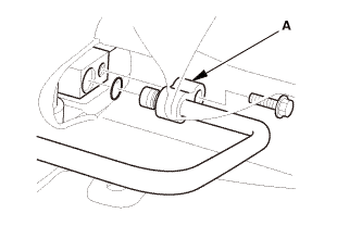
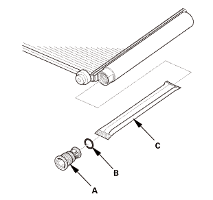
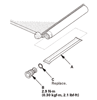
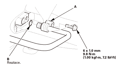
| 5. | A/C Line - Reconnection (A/C Condenser Side) |
|
1. |
Connect the receiver line (A) with a new O-ring (B) that is lubricated with clean refrigerant oil. |
|
|
|
 -m7.2
-m7.2| 6. | A/C System Evacuation |
|
| 7. | A/C Refrigerant - Charging |
|
1. |
Charge the system with the specified amount of R-134a refrigerant. Do not overcharge the system; the A/C compressor will be damaged. |
||||||||
|
Select the appropriate units of measure for your refrigerant charging station. |
|||||||||
|
|||||||||
| 8. | A/C Refrigerant - Leak Check |
|
Leak Detector Usage Tips (Refer to the Operator's Manual for complete operating instructions) |
|
|||
|
|||
|
|||
|
|||
|
|||
|
|||
|
|||
|
|||
|
Fluorescent Dye Usage Tips |
|
||||||||||||
|
||||||||||||
|
||||||||||||
|
||||||||||||
|
||||||||||||
|
|
1. |
With the engine OFF, use a halogen leak detector first to detect the leak source. Follow a continuous path in order to ensure that you will not miss any possible leaks. Test the following areas of the system for leaks: |
||||||||||||||||||||||||||||||||||||||||||||||||||||||||||||||||||||||||||
|
|||||||||||||||||||||||||||||||||||||||||||||||||||||||||||||||||||||||||||
|
2. |
Close the quick coupler valves, then disconnect the quick couplers from the vehicle service ports. |
|
3. |
Attach the universal connect set, from the Optimax Jr. Leak Detection Kit, to the service valve fitting. Close the control valve (the black knob on the connect set). |
|
4. |
Attach the charging station low pressure hose quick coupler to the service valve fitting, and open the quick coupler valve. Evacuate the connect set using the charging station vacuum pump, then close the quick coupler valve. |
|
5. |
Detach the universal connect set, and install a Tracer-Stick® dye capsule between the connect set and the service valve fitting (see the manufacturer's instructions for more detail). |
|
6. |
Attach the quick coupler on the universal connect set to the low pressure service port on the vehicle. Open the charging station low pressure hose quick coupler valve, but do not open the control valve. |
|
7. |
Start the engine, and set the A/C system to maximum cooling. Open the control valve to let refrigerant and the dye enter the A/C system through the low pressure service port. Close the control valve when the Tracer-Stick® dye capsule is empty. |
|
8. |
Run the engine and A/C system for 15 minutes to thoroughly circulate the dye. Then shut the engine off, and inspect the following areas of the system for leaks: |
|||||||||||||||||||||||||||||||||||||||||||||||||||||||||||||||||||||||||||||||
|
NOTE: |
||||||||||||||||||||||||||||||||||||||||||||||||||||||||||||||||||||||||||||||||
|
||||||||||||||||||||||||||||||||||||||||||||||||||||||||||||||||||||||||||||||||
|
||||||||||||||||||||||||||||||||||||||||||||||||||||||||||||||||||||||||||||||||
| 9. | A/C System - Test |
|
|
|
||||||||||||||||||||||||||||||||||||||||||||||||||||||||||||||||||||||||
|
6. |
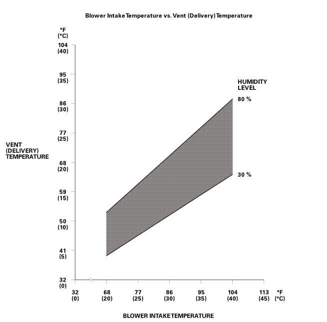
To complete the vent (delivery)/blower intake temperature chart: |
|||||||||||||||||
|
||||||||||||||||||
|
NOTE: The vent (delivery) temperature and blower intake temperature should intersect in the shaded area. Any measurements outside the line may indicate the need for further inspection. |
||||||||||||||||||
 orhuullnrrvlevel11vmrsono):277-rin)ian)amwinintaketemperature
|
7. |
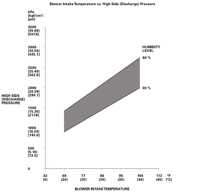
To complete the high side (discharge) pressure/blower intake temperature chart: |
|||||||||||||||||
|
||||||||||||||||||
|
NOTE: The high side (discharge) pressure and blower intake temperature should intersect in the shaded area. Any measurements outside the line may indicate the need for further inspection. |
||||||||||||||||||
 sun:highnuwuomlevel2217-s
|
8. |
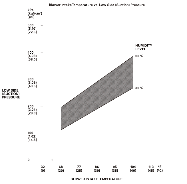
To complete the low side (suction) pressure/blower intake temperature chart: |
|||||||||||||||||
|
||||||||||||||||||
|
NOTE: The low side (suction) pressure and blower intake temperature should intersect in the shaded area. Any measurements outside the line may indicate the need for further inspection. |
||||||||||||||||||
 turn(suction)snnhuuunrrvlevel(sucnomzoo(am[am77-r(ulam
| 10. | Glove Box - Move |
|
|
|
| 11. | Front Bumper Absorber |
|
|
|
| 12. | Front Bumper |
|
|
|
|
|
|
|
|
|
|
|
|
| 13. | Front Grille Cover |
|
|
|
|
|
|
 A/C Compressor Relief Valve Removal and Installation (K24Z7)
614123
Air conditioning refrigerant or lubricant vapor can irritate
your eyes, nose, or throat.
...
 Compressor
...
See also:
Honda Civic Owners Manual. Making a Call
You can make calls by inputting any phone number, or by using the imported
phonebook, call history, speed dial entries, or redial.
Making a Call
Any voice-tagged speed dial entry can be dialed by
voice from any screen.
Press the button and follow
the prompts.
The ma ...
