Honda Civic Service Manual: Park Pin Switch Removal and Installation (A/T, CVT)

|
NOTE: Do not wipe off the special grease applied to the area of the shift
lever marked with an asterisk (*) when you disassemble it.
|
| 1. |
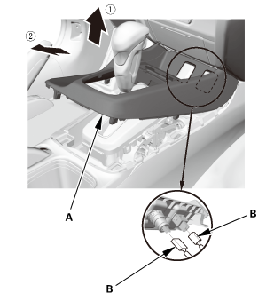
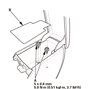
Center Console Panel Assembly (Except '12M M/T) |
|
|
|
2.
|
Remove the center console panel (A).
|
|
3.
|
For some models: Disconnect the connector(s) (B).
|
|
| 2. |
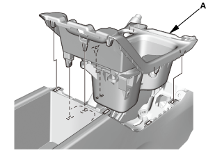
Cup Holder Panel Assembly |
|
|
|
1.
|
Remove the cup holder panel assembly (A).
|
|
| 3. |
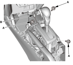
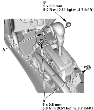
Center Console Assembly |
|
|
|
2.
|
Disconnect the connector (B).
|
|
|
|
|
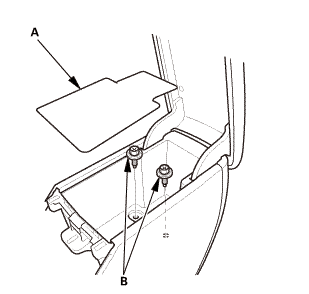
3.
|
Remove the console box mat (A).
|
|
|
|
|
5.
|
Disconnect the connector (A).
|
|
|

|
|
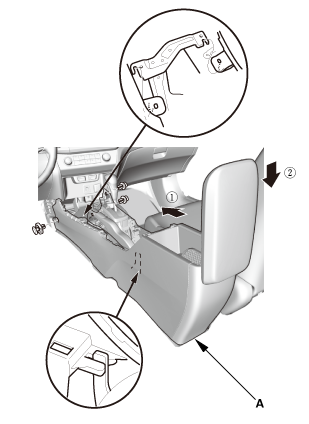
6.
|
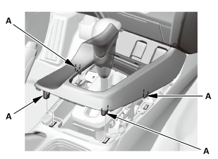
Remove the center console (A), in the numbered sequence shown.
|
|
| 4. |
Shift Lever Knob and Shift Lever Knob Ring |
|
|
|
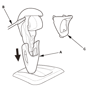
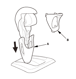
1.
|
Pull down the shift lever ring (A).
|
|
2.
|
Wrap the end of a flat-tip screwdriver (B) with tape, remove
the shift lever knob ring (C).
|
|
|
|
|
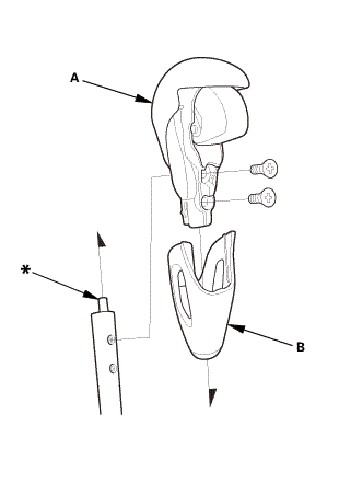
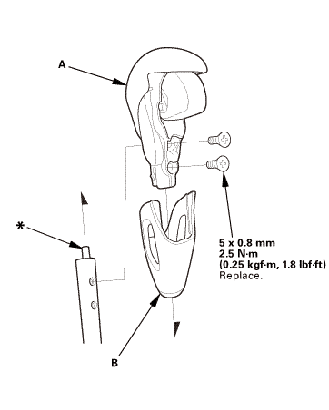
3.
|
Remove the shift lever knob (A) and the shift lever ring (B).
|
|
| 5. |
A/T Gear Position Indicator Panel Assembly (Type A Shift Lever) |
|

|
|
1.
|
Disconnect the connector (A).
|
|
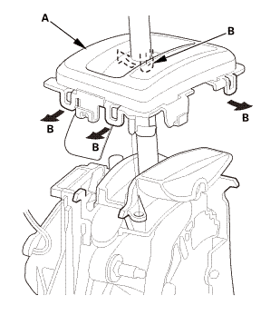
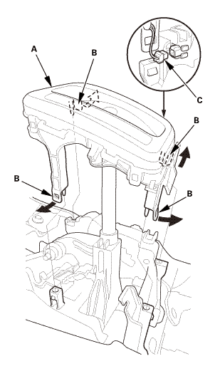
2.
|
Remove the A/T gear position indicator panel assembly (B) by
expanding the four lock tabs (C).
|
|
| 6. |
A/T Gear Position Indicator Panel Assembly (Type B Shift Lever) |
|
|
|
1.
|
Remove the A/T gear position indicator panel light socket (A).
|
|
2.
|
Remove the A/T gear position indicator panel light bulb (B).
|
|
3.
|
Unhook the A/T gear position indicator panel light harness (C)
from the harness guides.
|
|
|
|
|
4.
|
Remove the A/T gear position indicator panel assembly (A) by
expanding the four lock tabs (B).
|
|
| 7. |
Shift Lock Unit Assembly (Type A Shift Lever) |
|
|
|
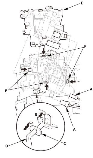
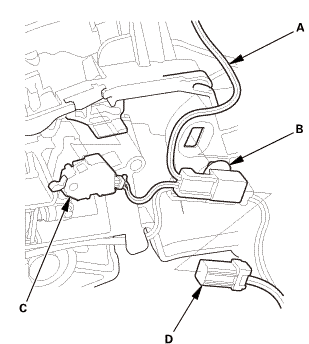
NOTE: The park pin switch and the shift lock unit are not available
separately. Replace the park pin switch and the shift lock unit
as a set.
|
|
1.
|
Disconnect the connectors (A).
|
|
2.
|
Release the lock tab (B) and turn the pivot pin (C) counterclockwise
using a hex wrench (D) as shown, and pull it.
|
|
3.
|
Remove the shift lock unit (E) while releasing the four lock
tabs (F).
|
|
| 8. |
Shift Lock Release (Type B Shift Lever) |
|
|
|
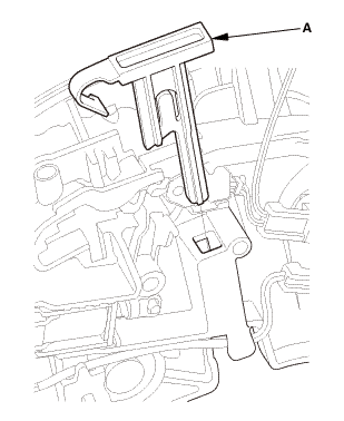
1.
|
Remove the shift lock release (A).
|
|
| 9. |
A/T Gear Position Indicator Panel Light Harness (Type B Shift Lever) |
|
|
|
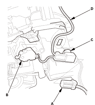
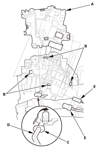
NOTE: The park pin switch and the A/T gear position indicator
panel light harness are not available separately. Replace the park
pin switch and the A/T gear position indicator panel light harness
as a set.
|
|
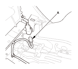
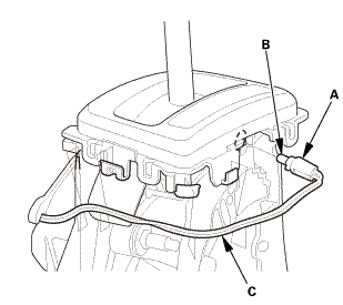
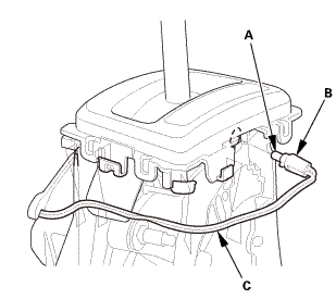
1.
|
Disconnect the connector (A).
|
|
2.
|
Remove the park pin switch (B).
|
|
3.
|
Remove the connector clamp (C), then remove the A/T gear position
indicator panel light harness (D).
|
|

|
NOTE: Do not wipe off the special grease applied to the area of the shift
lever marked with an asterisk (*) when you assemble it.
|
| 1. |
A/T Gear Position Indicator Panel Light Harness (Type B Shift Lever) |
|
|
|
1.
|
Install the A/T gear position indicator panel light harness (A),
then install the connector clamp (B).
|
|
2.
|
Install the park pin switch (C).
|
|
3.
|
Connect the connector (D).
|
|
| 2. |
Shift Lock Unit Assembly (Type A Shift Lever) |
|
|
|
1.
|
Install the shift lock unit (A) by aligning the four lock tabs
(B).
|
|
2.
|
Push the pivot pin (C), and turn it clockwise using a hex wrench
(D) as shown.
|
|
3.
|
Connect the connectors (E).
|
|
| 3. |
Shift Lock Release (Type B Shift Lever) |
|
|
|
1.
|
Install the shift lock release (A).
|
|
| 4. |
A/T Gear Position Indicator Panel Assembly (Type A Shift Lever) |
|
|
|
1.
|
Install the A/T gear position indicator panel assembly (A) by
aligning the four lock tabs (B).
|
|
2.
|
Connect the connector (C).
|
|
| 5. |
A/T Gear Position Indicator Panel Assembly (Type B Shift Lever) |
|
|
|
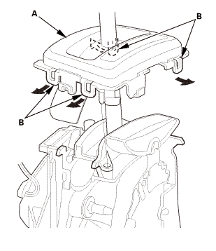
1.
|
Install the A/T gear position indicator panel assembly (A) by
aligning the four lock tabs (B).
|
|
|
|
|
2.
|
Install the A/T gear position indicator panel light bulb (A).
|
|
3.
|
Install the A/T gear position indicator panel light socket (B).
|
|
4.
|
Hook the A/T gear position indicator panel light harness (C)
to the harness guides.
|
|
| 6. |
Shift Lever Knob and Shift Lever Knob Ring |
|
1.
|
Install the shift lever knob (A) and the shift lever ring (B).
|
 mm
mm
|
|
|
2.
|
Pull down the shift lever ring (A) if necessary, and install
the shift lever knob ring (B).
|
|
3.
|
Pull up the shift lever ring to secure the knob ring.
|
|
| 7. |
Center Console Assembly |
|
|
|
1.
|
Install the center console (A), in the numbered sequence shown.
|
|
|
|
|
2.
|
Connect the connector (A).
|
|
|
|
|
3.
|
Install the bolts (A).
|
|
4.
|
Install the console box mat (B).
|
|
|
 mms.n mms.n
|
|
5.
|
Connect the connector (A).
|
|
6.
|
Install the bolts (B).
|
|
| 8. |
Cup Holder Panel Assembly |
|
|
|
1.
|
Install the cup holder panel assembly (A).
|
|
| 9. |
Center Console Panel Assembly (Except '12M M/T) |
|

|
|
1.
|
For some models: Connect the connector(s) (A).
|
|
2.
|
Install the center console panel (B).
|
|
|
|
|
3.
|
Install the clips (A).
|
|
2181D9
Removal
1.
Air Cleaner
1.
Disconnect the intake air duct (A).
...
2191M0 RIGHT
1.
Vehicle Lift
1.
Raise the vehicle on a lift, and make sure it is securely supported.
...
 Output Shaft (Countershaft) Speed Sensor Removal and Installation (A/T)
 Right A/T Differential Oil Seal Replacement (A/T)