Honda Civic Service Manual: Intake Manifold Removal and Installation (R18Z1)
 View
View
| 1. |
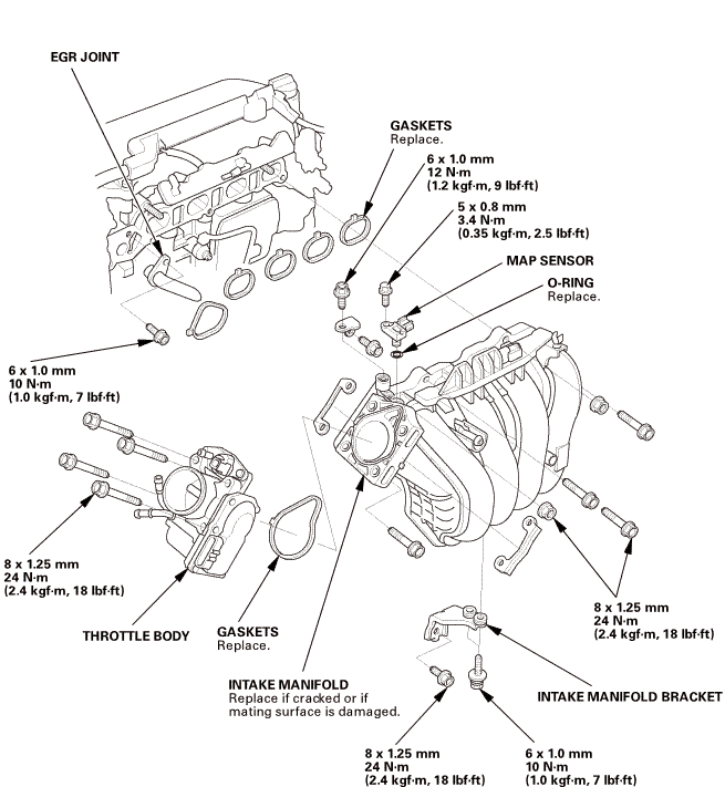
Intake Manifold Exploded View |
 max:manifold.msl.mjoinyaonvmanifoldivorivmulinv

Removal
|
NOTE: Refer to the Exploded View if needed during this procedure.
|
|
|
|
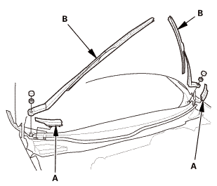
NOTE: Set the wiper arms to the auto-stop position before removal.
|
|
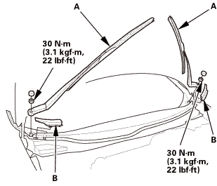
1.
|
Remove the cowl top wiper covers (A).
|
|
2.
|
Remove the wiper arms (B).
|
|
|
|
|
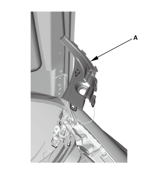
1.
|
Remove the side cowl cover (A).
|
|
2.
|
The left side is shown; repeat on the right side.
|
|
|

|
|
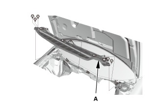
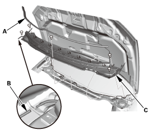
1.
|
Remove the center cowl cover (A).
|
|
2.
|
Disconnect the windshield washer tube (B).
|
|
3.
|
If necessary, remove the hood rear seal (C).
|
|
|
|
|
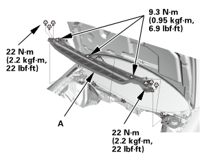
1.
|
Remove the under cowl panel (A).
|
|
|
|
1.
|
Remove the fuel fill cap to relieve the pressure in the fuel
tank.
|
|
|
|
|
NOTE: For specific operations, refer to the user's manual that
came with the Honda Diagnostic System (HDS). Make sure the HDS is
loaded with the latest software.
|
|
1.
|
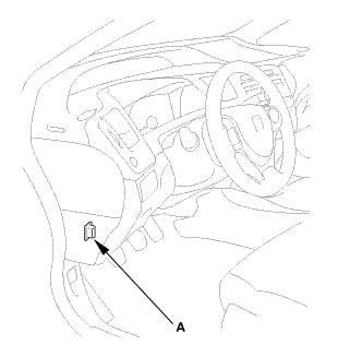
Connect the HDS to the data link connector (DLC) (A) located
under the driver's side of the dashboard.
|
|
2.
|
Turn the ignition switch to ON (II).
|
|
3.
|
Make sure the HDS communicates with the vehicle. If it does not
communicate, go to the DLC circuit troubleshooting.
|
|
|
|
1.
|
Turn the ignition switch to ON (II).
|
|
2.
|
From the INSPECTION MENU of the HDS, select Fuel Pump OFF, then
start the engine, and let it idle until it stalls.
|
|
NOTE:
|
|

|
Do not allow the engine to idle above 1,000 rpm
or the ECM/PCM will continue to operate the fuel
pump.
|
|
|
|
Pending or Confirmed DTC may be set during this
procedure. Check for DTCs, and clear them as needed.
|
|
|
|
3.
|
Turn the ignition switch to LOCK (0).
|
|
| 8. |
Battery Terminal - Disconnection |
|
|
|
1.
|
Make sure the ignition switch is in LOCK (0).
|
|
2.
|
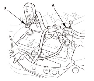
Disconnect and isolate the negative cable and battery sensor
(A) from the battery.
|
|
NOTE: Always disconnect the negative side first.
|
|
3.
|
Disconnect the positive cable (B) from the battery.
|
|
| 9. |
Fuel Pressure - Relieving |
|
|
|
1.
|
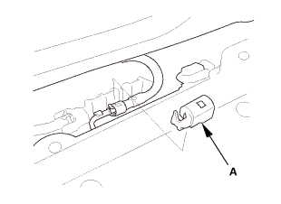
Remove the quick-connect fitting cover (A).
|
|
2.
|
Check the fuel quick-connect fitting for dirt, and clean it if
needed.
|
|
|
|
|
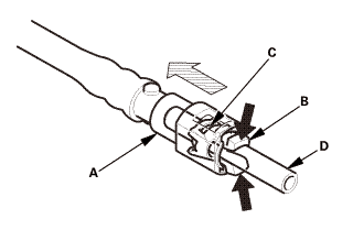
3.
|
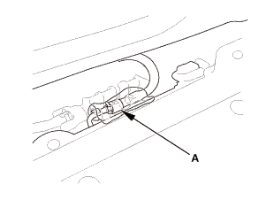
Place a rag or shop towel over the quick-connect fitting (A).
|
|
|
|
|
4.
|
Disconnect the quick-connect fitting: Hold the connector (A)
with one hand, and squeeze the retainer tabs (B) with the other
hand to release them from the locking tabs (C). Pull the connector
off.
|
|
NOTE:
|
|
|
Be careful not to damage the line (D) or other
parts.
|
|
|
|
Do not use tools.
|
|
|
|
If the connector does not move, keep the retainer
tabs pressed down, and alternately pull and push
the connector until it comes off easily.
|
|
|
|
Do not remove the retainer from the line; once
removed, the retainer must be replaced with a new
one.
|
|
|
|
|
|
|
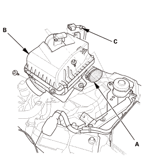
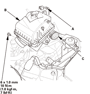
1.
|
Disconnect the intake air duct (A).
|
|
2.
|
Remove the air cleaner (B).
|
|
3.
|
Remove the harness clamp (C).
|
|
|
|
|
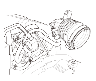
1.
|
Remove the intake air duct.
|
|
| 12. |
Throttle Body - Removal |
|
|
|
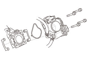
1.
|
Remove the throttle body without disconnecting the hoses.
|
|
| 13. |
Intake Manifold Assembly |
|
|
|
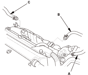
1.
|
Disconnect the EVAP canister hose (A), the brake booster vacuum
hose (B), and the PCV hose (C).
|
|
|
|
|
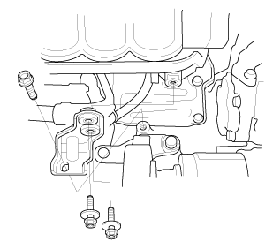
2.
|
Remove the heater hose clamp bracket.
|
|
|
|
|
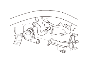
3.
|
Remove the intake manifold bracket.
|
|
|
|
|
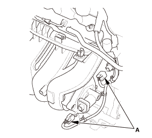
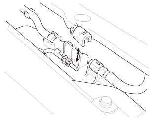
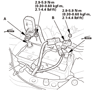
4.
|
Disconnect the connectors (A).
|
|
5.
|
Remove the harness clamps.
|
|
|
|
|
6.
|
Remove the intake manifold assembly.
|
|

Installation
|
NOTE: Refer to the Exploded View if needed during this procedure.
|
| 1. |
Intake Manifold Assembly |
|
 mm mm
|
|
1.
|
Install the intake manifold assembly (A) with new gaskets (B).
|
|
2.
|
Tighten the bolts/nuts in a crisscross pattern in three steps,
beginning with the inner bolt.
|
|
|
|
|
3.
|
Install the connectors (A).
|
|
4.
|
Connect the harness clamps.
|
|
|
|
|
5.
|
Install the intake manifold bracket.
|
|
|

|
|
6.
|
Install the heater hose clamp bracket.
|
|
|
|
|
7.
|
Connect the EVAP canister hose (A), the brake booster vacuum
hose (B), and the PCV hose (C).
|
|
| 2. |
Throttle Body - Installation |
|
 mm mm
|
|
1.
|
Install the throttle body (A) with new O-ring (B).
|
|
|
|
|
1.
|
Install the intake air duct.
|
|
|
|
|
1.
|
Install the harness clamp (A).
|
|
2.
|
Install the air cleaner (B).
|
|
3.
|
Connect the intake air duct (C).
|
|
| 5. |
Injector Base Fuel Feed Hose - Reconnection |
|
|
|
1.
|
Connect the fuel feed hose.
|
|
|
 22mm)2222 22mm)2222
|
|
1.
|
Install the under cowl panel (A).
|
|
|
|
|
1.
|
If necessary, install the hood rear seal (A).
|
|
2.
|
Connect the windshield washer tube (B).
|
|
3.
|
Install the center cowl cover (C).
|
|
|
|
|
1.
|
Install the side cowl cover (A).
|
|
2.
|
The left side is shown; repeat on the right side.
|
|
|
 1.122 1.122
|
|
NOTE: Set the wiper arms to the auto-stop position before installation.
|
|
1.
|
Install the wiper arms (A).
|
|
2.
|
Install the cowl top wiper covers (B).
|
|
|
|
1.
|
Install the fuel fill cap.
|
|
| 11. |
Battery Terminal - Reconnection |
|
|
|
NOTE: If the battery performs abnormally, test the battery.
|
|
1.
|
Clean the battery terminals.
|
|
2.
|
Connect the positive cable (A) to the battery.
|
|
NOTE: Always connect the positive side first.
|
|
3.
|
Connect the negative cable and battery sensor (B) to the battery.
|
|
4.
|
Apply multipurpose grease to the terminals to prevent corrosion.
|
|
|

|
|
1.
|
Connect the HDS to the data link connector (DLC) (A) located
under the driver's side of the dashboard.
|
|
2.
|
Turn the ignition switch to ON (II).
|
|
3.
|
Make sure the HDS communicates with the vehicle. If it does not
communicate, go to the DLC circuit troubleshooting.
|
|
|
|
1.
|
From the INSPECTION MENU of the HDS, select Fuel Pump ON.
|
|
NOTE: Pending or Confirmed DTC may be set during this procedure.
Check for DTCs, and clear them as needed.
|
|
2.
|
Turn the ignition switch to LOCK (0).
|
|
|
|
1.
|
Turn the ignition switch to ON (II) (but do not operate the starter
motor). The fuel pump runs for about 2 seconds, and fuel pressure
rises. Repeat this two or three times, then make sure there are
no fuel leaks.
|
|
| 15. |
Tubes, Hoses, and Connectors After Installation Check |
|
|
1.
|
After installation, check that all tubes, hoses, and connectors
are installed correctly.
|
|
View
1.
Intake Manifold Exploded View (Natural Gas Model)
Exploded View
Removal
NOTE: Refer to the Exploded View if needed during this pr ...
 Intake Manifold Removal and Installation (R18A9)
