Honda Civic Service Manual: Front Wheel Bolt Removal and Installation (Si models)

| 1. | Vehicle Lift |
|
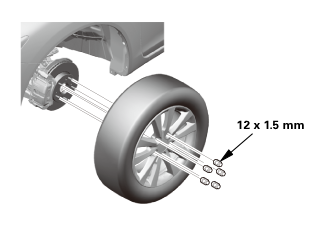
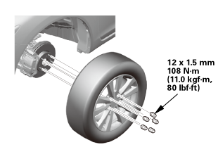
| 2. | Front Wheel |
|
|
|
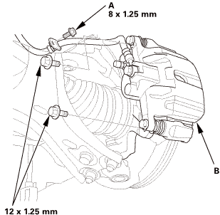
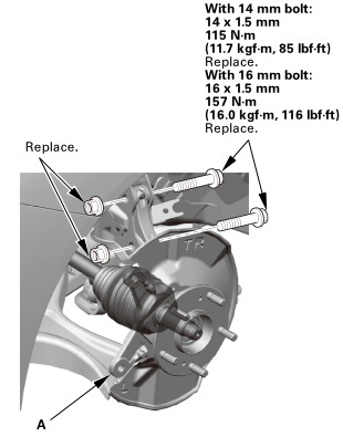
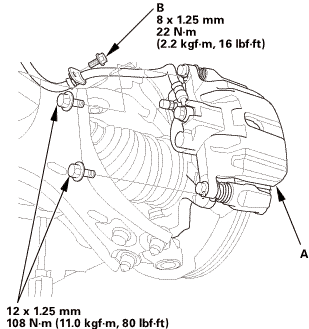
| 3. | Front Brake Caliper - Detach |
|
|
|
||||||||||||||||||||
 115mm
115mm
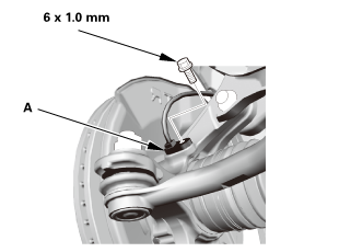
| 4. | Front Wheel Speed Sensor - Move |
|
|
|
||||||
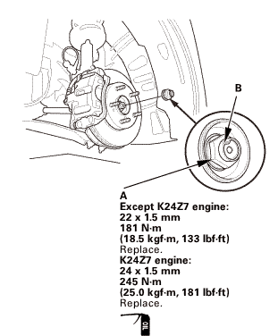
| 5. | Driveshaft Spindle Nut, Front Left |
|
|
|
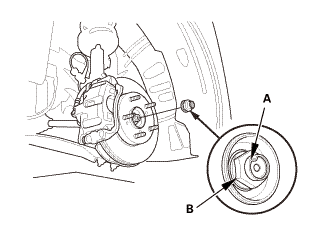
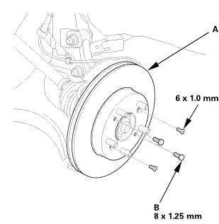
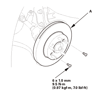
| 6. | Front Brake Disc |
|
|
|
||||||
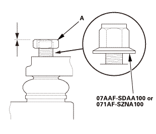
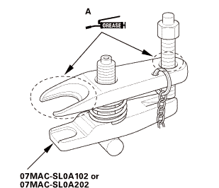
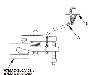
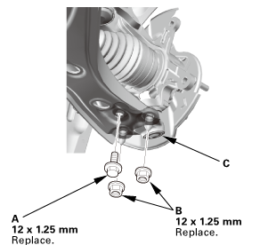
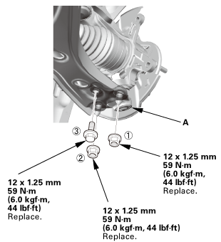
| 7. | Ball Joint - Removal |
|
|
Always use a ball joint remover to disconnect a ball joint. Do not strike the housing or any other part of the ball joint connection to disconnect it.
|
||||||

|
|
|
 ov
ov|
|
|
||||||||||||||||||||||||||||||||
 wmae-sldaidz
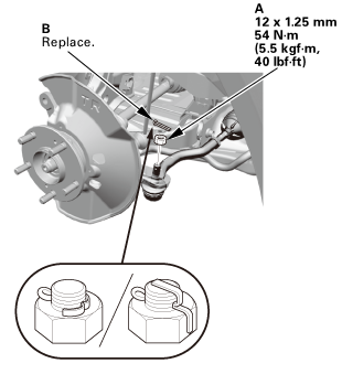
| 8. | Tie-Rod End Ball Joint - Disconnection |
|
|
|
| 9. | Lower Ball Joint Lower Arm Side - Disconnection |
|
|
|
 i225
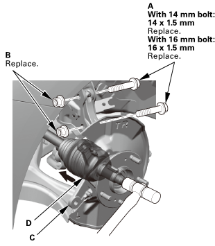
i225| 10. | Front Knuckle/Hub Assembly |
|
|
|
|||||||||
 v\r.n.v\r.n.ii
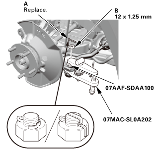
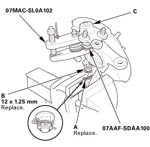
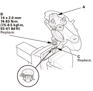
| 11. | Front Lower Ball Joint |
|
|
|
| 12. | Front Wheel Hub |
|
|
|
||||||
 i7.wheelo7gafsma1oo
|
|
|
 pun17,1:il7gafsei!i)li)il17,1:
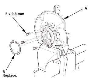
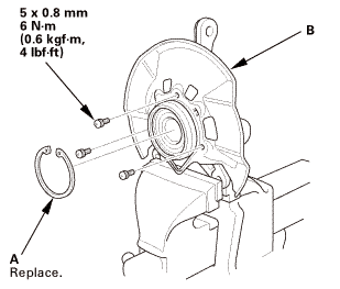
| 13. | Front Splash Guard and Snap Ring |
|
|
|
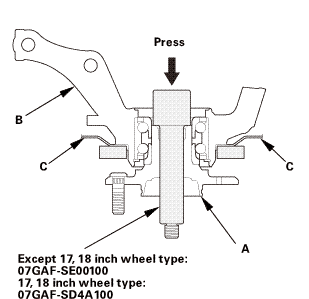
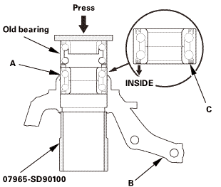
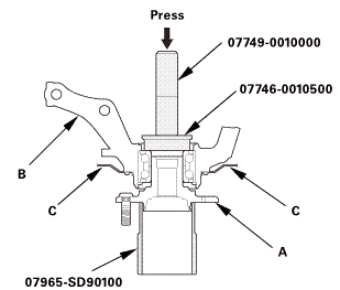
| 14. | Front Wheel Bearing |
|
|
|
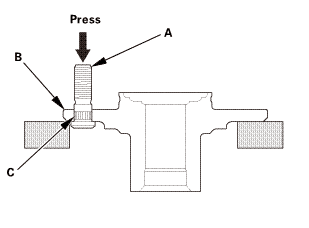
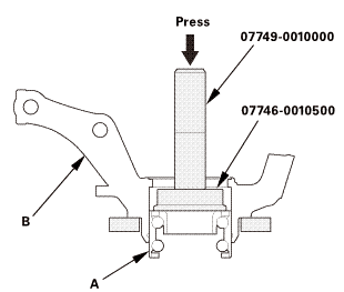 pressn774somosno
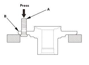
| 15. | Front Wheel Bolt |
|
|
|

|
NOTE: If you cannot tighten the wheel nut to the specified torque when installing the wheel, replace the front hub bearing unit as an assembly. |
| 1. | Front Wheel Bolt |
|
|
|
||||||||||||||||||||||||
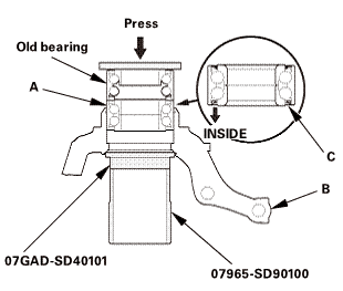
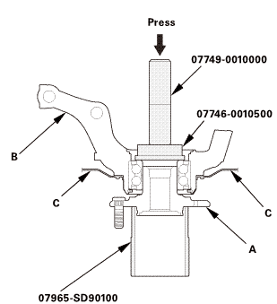
| 2. | Front Wheel Bearing |
|
Except 17, 18 inch wheel type
17, 18 inch wheel type
|
|
|||||||||
| 3. | Front Splash Guard and Snap Ring |
|
|
|
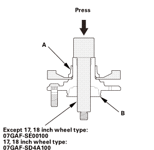
| 4. | Front Wheel Hub |
|
Except 17, 18 inch wheel type
17, 18 inch wheel type
|
|
||||||
 press
press| 5. | Front Lower Ball Joint |
|
Except 18 inch wheels
18 inch wheel
|
|
||||||||||||

| 6. | Front Knuckle/Hub Assembly |
|
Except 18 inch wheel
18 inch wheel
|
|
||||||
 wmmmmmm115mmm.1immwmmmmmm151mmm,mwu
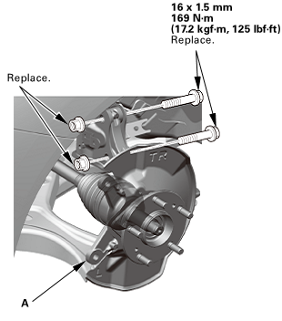 inmminu-m(17.2125
| 7. | Lower Ball Joint Lower Arm Side - Reconnection |
|
|
|
 55(ini15mm(skg!m,12x125mm
| 8. | Tie-Rod End Ball Joint - Reconnection |
|
|
|
 i2mmonum
| 9. | Front Brake Disc |
|
|
|
||||||
| 10. | Driveshaft Spindle Nut, Front Left |
|
|
|
 22x15mm15mm
| 11. | Front Wheel Speed Sensor - Move |
|
|
|
 lomm
lomm| 12. | Front Brake Caliper - Reattach |
|
|
|
 mm
mm| 13. | Front Wheel |
|
|
|
||||||
 mmmln-mnomm
| 14. | Pre-Alignment Checks |
|
| 15. | Caster - Inspection |
|
|||||||||||||||||||||||||||||||||||||||||||||||
| 16. | Camber - Inspection |
|
||||||||||||||||||||||||||||||||||||||||||||||||||||||||||||||||||||||||||||||||||||||
| 17. | Front Toe - Inspection |
|
|||||||||||||||||||||||||
| 18. | Turning Angle - Inspection |
|
|
|
|||||||||||||||||||||||||||||||||||||||||||||||||||||||||||||||||||||||||||||||||||||||||
|
|
|
|||||||||||||||||||||||||||||||||||||||||||||||||||||||||
 Front Wheel Bolt Removal and Installation (Except Si models)
4151B0 LEFT FRONT
4151B1 RIGHT FRONT
1.
Vehicle Lift
1.
Raise the vehicle on a lift, and make sure it is securely suppor ...
 Wheel Runout Inspection
1.
Vehicle Lift
1.
Raise the vehicle on a lift, and make sure it is securely supported.
2. ...
See also:
Honda Civic Owners Manual. How to Select a Song from the Music Search List with the Selector Knob
1. Press to display the
music search list.
2. Rotate to select a category.
3. Press to display a list
of items in the
category.
4. Rotate to select an item,
then press .
Press and rotate
repeatedly until a
desired item you want to listen ...
