Honda Civic Service Manual: Engine Oil Pump Removal and Installation (Except K24Z7)
111150

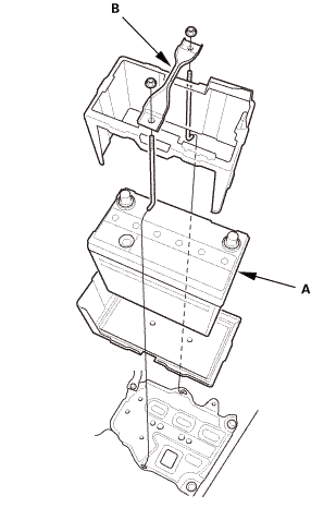
| 1. | Battery Terminal - Disconnection |
|
|
|
|||||||||||||||||||||||||||
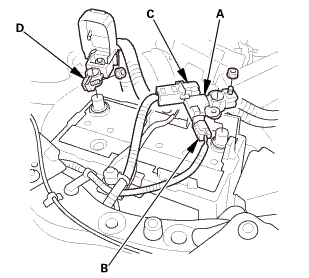

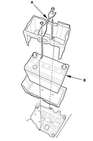
| 2. | Battery |
|
|
|
| 3. | Vehicle Lift |
|
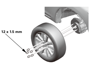
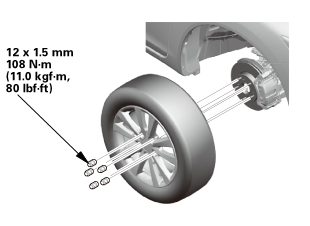
| 4. | Tire and Wheel-Removal, Front Right |
|
|
|
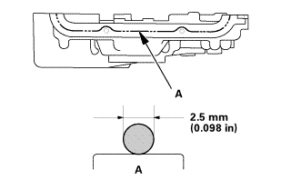
 12x1mm
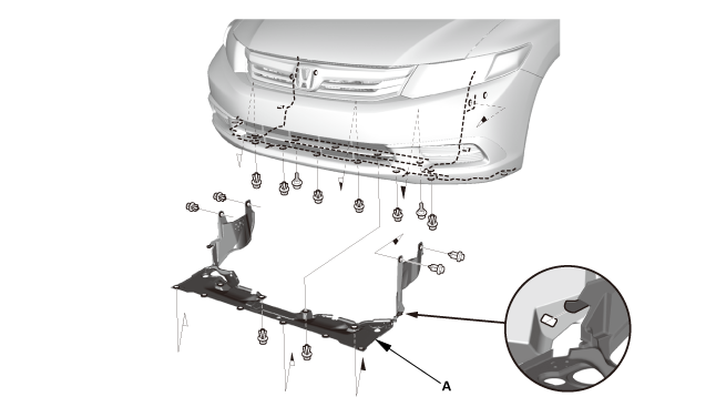
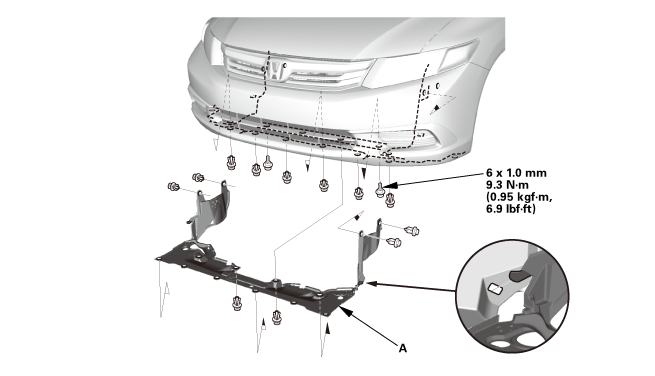
| 5. | Splash Shield |
|
1. |
Remove the splash shield (A). |
| 6. | Water Pump Pulley Mounting Bolt - Loosen |
|
|
|
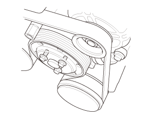
| 7. | Drive Belt |
|
|
|
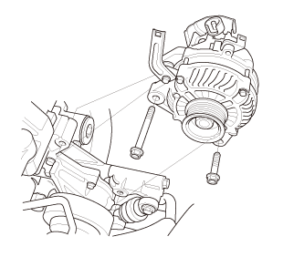
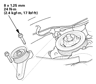
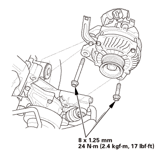
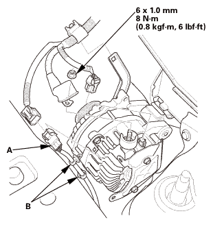
| 8. | Alternator |
|
|
|
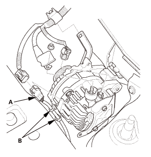
|
|
|
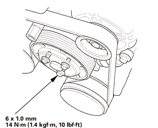
| 9. | Water Pump Pulley |
|
|
|
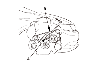
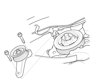
| 10. | Auto Tensioner Assembly |
|
|
|
| 11. | Idler Pulley Base Assembly |
|
|
|
| 12. | Engine Cover |
|
|
|
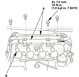
| 13. | Cylinder Head Cover Peripheral Assembly |
|
|
|
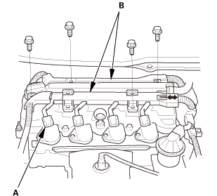
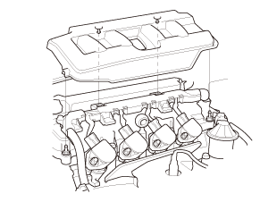
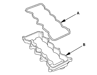
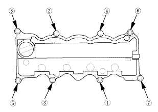
| 14. | Cylinder Head Cover and/or Packing |
|
|
|
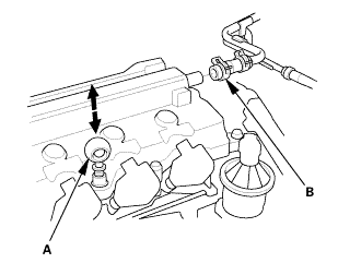
|
|
|
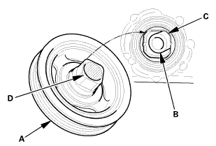
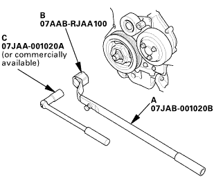
| 15. | Crankshaft Pulley |
|
|
|
 [av
[av| 16. | Engine Jack Support (State Of A Low Vehicle) |
|
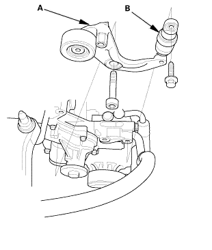
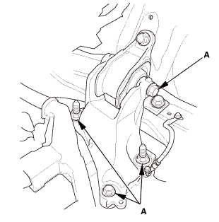
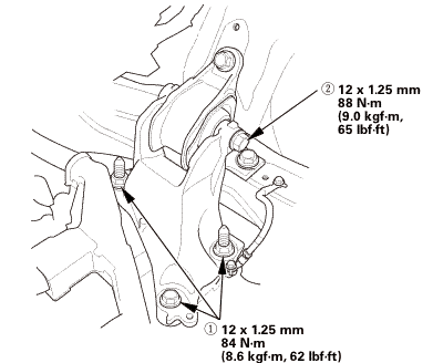
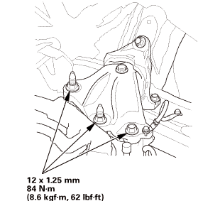
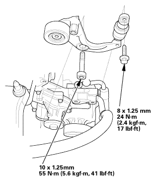
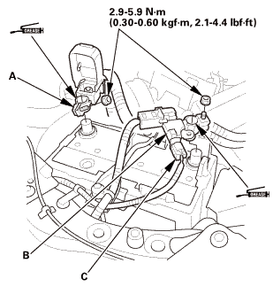
| 17. | Mounting Bracket, Engine Side |
|
|
|
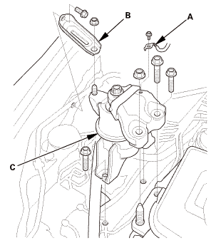
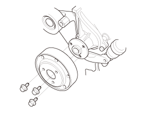
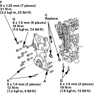
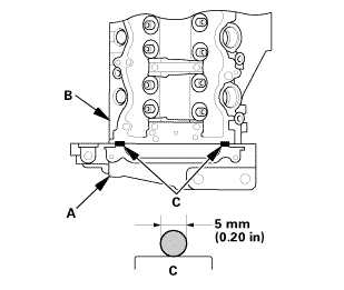
| 18. | Engine Oil Pump Assembly |
|
|
|
|
|
|
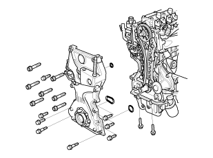

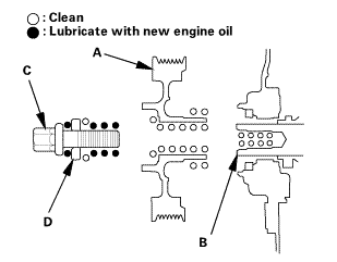
| 1. | Engine Oil Pump Assembly |
|
|
|
||||||||||||||||||||||||||
|
|
|
||||||||||||||
|
|
|
||||||||||||||||||||||||||||||
 25mm(7(32k1n1omm12
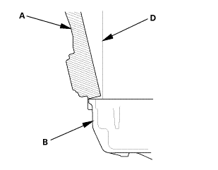
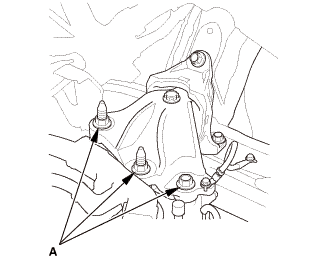
| 2. | Mounting Bracket, Engine Side |
|
|
|
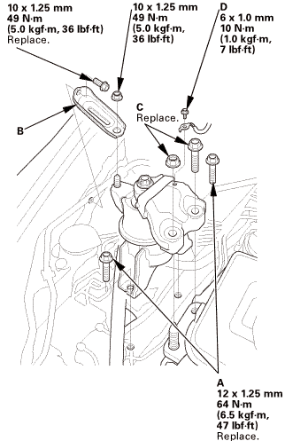 125mmnminm.:125mm
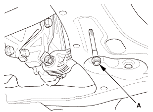
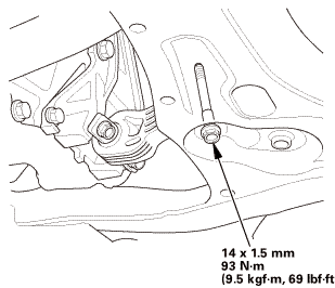
| 3. | Engine Jack Support (State Of A Low Vehicle) |
|
| 4. | Transmission Mount Bracket Mounting Bolt - Loosen |
|
M/T
A/T
|
|
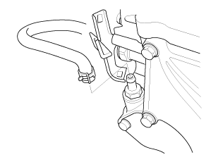
| 5. | Lower Torque Rod - Loosen |
|
|
|
| 6. | Side Engine Mount - Tighten |
|
|
|
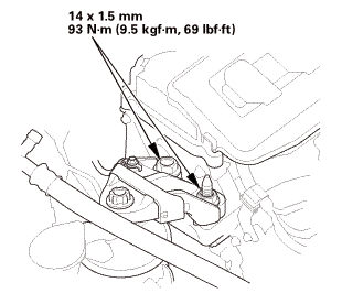 nxl.mm
| 7. | Transmission Mount Bracket Mounting Bolt - Tighten |
|
1. |
Tighten the transmission mount bracket mounting bolt and nuts. |
M/T
 i2mm
i2mm
A/T
 nz
nz
| 8. | Lower Torque Rod Mounting Bolt - Tighten |
|
|
|
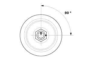
| 9. | Crankshaft Pulley |
|
|
|
|
|
|
|
|
|
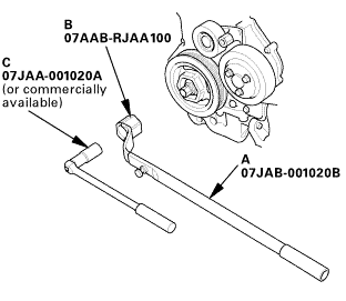
|||||||||||||
 o7jaanmo2oa
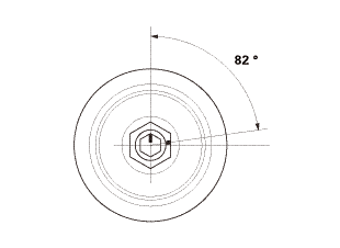
|
|
|
||||||||||
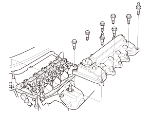
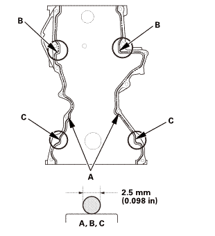
| 10. | Cylinder Head Cover and/or Packing |
|
|
|
|||||||||||||||
|
|
|
||||||||||||||||||||
|
|
|
||||||||||||||||||||
|
|
|
| 11. | Cylinder Head Cover Peripheral Assembly |
|
|
|
 mmidnmm,
| 12. | Engine Cover |
|
|
|
| 13. | Idler Pulley Base Assembly |
|
|
|
| 14. | Auto Tensioner Assembly |
|
|
|
 inl.25mmssn-m
| 15. | Water Pump Pulley |
|
|
|
| 16. | Alternator |
|
|
|
 mmn-m(2
|
|
|
 i.nmm(n.i
| 17. | Drive Belt |
|
|
|
| 18. | Water Pump Pulley Mounting Bolt - Tighten |
|
|
|
| 19. | Splash Shield |
|
1. |
Install the splash shield (A). |
| 20. | Tire and Wheel-Installation, Front Right |
|
|
|
||||||
 mminmuan
| 21. | Battery |
|
|
|
||||||
| 22. | Battery Terminal - Reconnection |
|
|
|
|||||||||||||||||||
 Engine Oil Pump Overhaul (K24Z7)
View
1.
Oil Pump Exploded View
Exploded View
mm27allon.pumpnowel......-m(1.2holder/bysoninbore
Disassembly
NOTE: Refer to the Exploded View ...
 Engine Block Drain Bolt/Sealing Bolt Removal and Installation (Except K24Z7)
Replacement
1.
Sealing Bolt
NOTE: When installing the drain bolt and/or sealing bolt, always use
new washers.
l.5mm75mm35mmmmkglm,i25mm75
...
See also:
Honda Civic Owners Manual. Continuously Variable Transmission (CVT) Fluid
Models with continuously variable transmission
Specified fluid: Honda HCF-2 Transmission Fluid
Have a dealer check the fluid level and replace if necessary.
Do not attempt to check or change the continuously variable transmission fluid
yourself
Continuously Variable Transmission (C ...
