Honda Civic Service Manual: Engine Oil Pump Overhaul (K24Z7)
 View
View
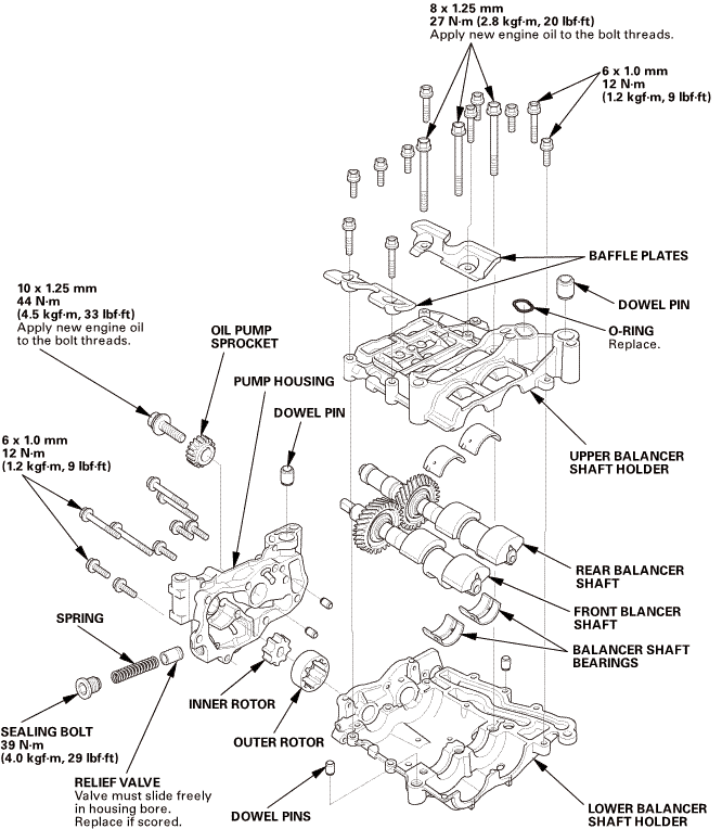
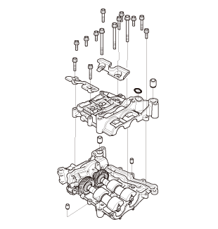
| 1. | Oil Pump Exploded View |
|
Exploded View |
 mm27allon.pumpnowel......-m(1.2holder/bysoninbore
 Disassembly
|
NOTE: Refer to the Exploded View if needed during this procedure. |
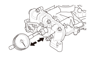
| 1. | Engine Oil Pump Balancer Shaft End Play - Inspection |
|
1. |
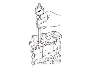
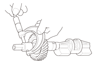
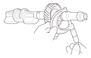
Zero the dial indicator against the end of the rear balancer shaft, then push the rear balancer shaft back and forth and read the end play. |
|||||||||
|
||||||||||
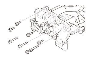
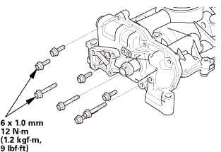
| 2. | Engine Oil Pump Housing |
|
|
|
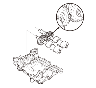
| 3. | Engine Oil Pump Balancer Shaft |
|
|
|

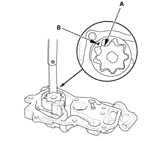
| 4. | Engine Oil Pump - Inspection |
|
1. |
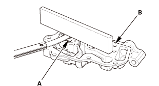
Align the tip of the inner rotor tooth (A) with the mark (B) on the outer rotor, then check the inner rotor-to-outer rotor radial clearance between the inner rotor and the outer rotor. If the inner rotor-to-outer rotor radial clearance exceeds the service limit, replace the oil pump. |
|||||||||
|
||||||||||
|
2. |
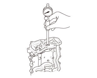
Check the pump housing-to-rotor axial clearance between the rotor (A) and the pump housing (B). If the pump housing-to-rotor axial clearance exceeds the service limit, replace the oil pump. |
|||||||||
|
||||||||||
|
3. |
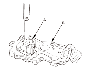
Check the pump housing-to-outer rotor radial clearance between the outer rotor (A) and the pump housing (B). If the pump housing-to-outer rotor radial clearance exceeds the service limit, replace the oil pump. |
|||||||||
|
||||||||||
| 5. | Engine Oil Pump Balancer Shaft - Inspection |
|
1. |
Measure the inner diameters of the No. 1 bearing for the front balancer shaft hole and the rear balancer shaft hole. |
|||||||||||||||||
|
||||||||||||||||||
Front
Rear
|
Front
Rear
|
|
|
|
|
|
6. |
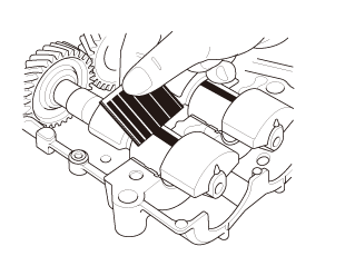
Remove the upper balancer shaft holder and the bearings again, and measure the widest part with the plastigage. If the balancer shaft No. 2 journals oil clearance is out-of-tolerance, install new bearings, and recheck. If it is still out-of-tolerance, replace the balancer shafts. |
|||||||||
|
||||||||||
 Reassembly
|
NOTE: Refer to the Exploded View if needed during this procedure. |
| 1. | Engine Oil Pump Balancer Shaft |
|
|
|
|
|
|
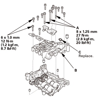
| 2. | Engine Oil Pump Housing |
|
|
|
 Engine Oil/Air Separator Removal and Installation (R18Z1)
1111M5
Removal
1.
Wiper Arm Assembly
NOTE: Set the wiper arms to the auto-stop position before removal.
...
 Engine Oil Pump Removal and Installation (Except K24Z7)
111150
1.
Battery Terminal - Disconnection
1.
Make sure the ignition switch is in LOCK (0), or the vehicle
...
See also:
Honda Civic Service Manual. Headlight Adjustment ('12-'13, '14: 4-door)
1.
Headlight - Adjustment
Headlights become very hot during use; do not touch them or any
attaching hardware immediately after they have been turned off.
Before adju ...
