Honda Civic Service Manual: Cruise Control Combination Switch Removal, Installation, and Test
738125

Removal
|
There are SRS components located in this area. Review the SRS component
locations, and the precautions and procedures, in the SRS before doing repairs
or service.
|
| 1. |
Battery Terminal (SRS) - Disconnection |
|
|
|
1.
|
Make sure the ignition switch is in LOCK (0).
|
|
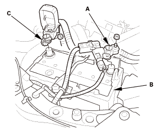
2.
|
Disconnect and isolate the negative cable and battery sensor
(A) from the battery (B).
|
|
NOTE: Always disconnect the negative side first.
|
|
3.
|
Disconnect the positive cable (C) from the battery.
|
|
4.
|
Wait at least 3 minutes before starting work.
|
|
|
|
|
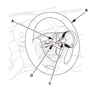
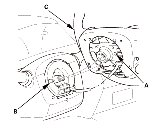
1.
|
Remove the access panel (A).
|
|
2.
|
Disconnect the driver's airbag inflator connector (B) on the
cable reel harness.
|
|
3.
|
Disconnect the horn switch connector (C).
|
|
|
|
|
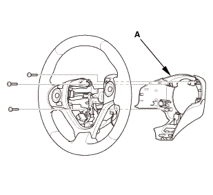
4.
|
Remove the TORX bolts using a TORX T30 bit.
|
|
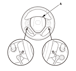
5.
|
Remove the driver's airbag (A).
|
|
| 3. |
Steering Wheel Assembly |
|
 wxusmm wxusmm
|
|
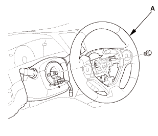
1.
|
Set the front wheels in the straight ahead position.
|
|
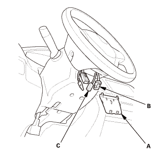
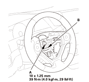
2.
|
Disconnect the connector (A).
|
|
3.
|
Loosen the steering wheel bolt (B) three turns.
|
|
|
|
|
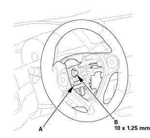
4.
|
Install a commercially available steering wheel puller (A) on
the steering wheel (B).
|
|
5.
|
Free the steering wheel from the steering column shaft by turning
the pressure bolt (C) of the puller.
|
|
Note these items when removing the steering wheel:
|
|

|
Do not tap on the steering wheel or the steering
column shaft when removing the steering wheel.
|
|
|
|
If you thread the puller bolts (D) into the wheel
hub more than five threads, the bolts will hit the
cable reel and damage it. To prevent this, install
a pair of jam nuts five threads up on each puller
bolt.
|
|
|
|
|
|
|
6.
|
Remove the steering wheel puller.
|
|
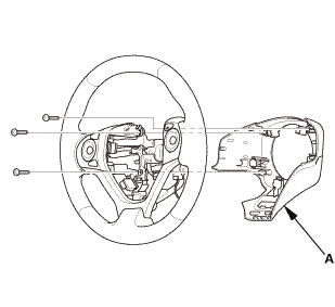
7.
|
Remove the steering wheel (A) from the steering column.
|
|
| 4. |
Steering Wheel Rear Cover |
|
|
|
1.
|
Remove the steering wheel rear cover (A).
|
|
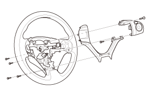
| 5. |
CRUISE CONTROL COMBINATION SWITCH |
|
|
|
1.
|
Remove the cruise control combination switch.
|
|
 Test
Test
| 1. |
CRUISE CONTROL COMBINATION SWITCH - TEST |
|
|
|
1.
|
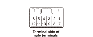
Measure the resistance between cruise control combination switch
12P connector terminal No. 2 and No. 5 according to the table.
|
|
If there is no resistance in one or more positions, replace the
cruise control combination switch.
|
|
|
Position
|
Resistance
|
|
OFF
|
About 2.2 k?
|
|
Cruise control main (PRESSED)
|
About 60 ?
|
|
Cancel (PRESSED)
|
About 190 ?
|
|
Set/- (PRESSED)
|
About 450 ?
|
|
Res/+ (PRESSED)
|
About 900 ?
|
|
|
|
|
|
 pusllwnswilch(am pusllwnswilch(am
|
|
2.
|
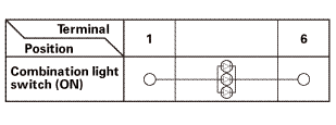
Check for continuity between cruise control combination switch
12P connector terminal No. 1 and No. 6 according to the table.
|
|
If there is no continuity, replace the cruise control combination
switch.
|
|

Installation
|
There are SRS components located in this area. Review the SRS component
locations, and the precautions and procedures, in the SRS before doing repairs
or service.
|
| 1. |
CRUISE CONTROL COMBINATION SWITCH |
|
|
|
1.
|
Install the Install the cruise control combination switch.
|
|
| 2. |
Steering Wheel Rear Cover |
|
|
|
1.
|
Install the steering wheel rear cover (A).
|
|
| 3. |
Steering Wheel Assembly |
|
|
|
1.
|
Make sure the front wheels are pointing straight ahead.
|
|
2.
|
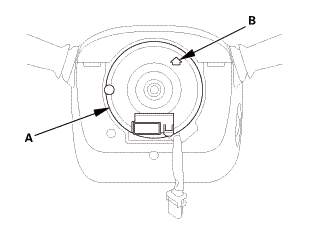
Center the cable reel (A). Do this by first rotating the cable
reel clockwise until it stops.
|
|
3.
|
Rotate the cable reel counterclockwise about three full turns.
The arrow mark (B) on the cable reel label should point straight
up.
|
|
|
|
|
4.
|
Position the steering wheel hub (A) so that it engages the pin
(B) of the cable reel.
|
|
5.
|
Install the steering wheel (C) on to the steering column shaft.
|
|
NOTE: Do not tap on the steering wheel or the steering column
shaft when installing the steering wheel.
|
|
|
 no no
|
|
6.
|
Install the steering wheel bolt (A), and tighten it to the specified
torque.
|
|
7.
|
Connect the connector (B).
|
|
8.
|
Make sure the wire harness is routed and fastened properly.
|
|
|
 mmmmin)in! mmmmin)in!
|
|
NOTE: If you are replacing a deployed driver's airbag, inspect
the cable reel for heat damage. If there is any damage, replace
the cable reel.
|
|
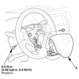
1.
|
Place the driver's airbag (A) in the steering wheel.
|
|
2.
|
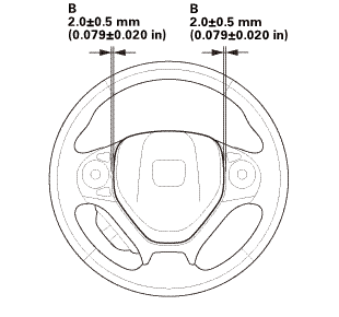
Tighten the new TORX bolts using a TORX T30 bit.
|
|
NOTE: Make sure the clearance (B) between the steering wheel
and horn pad is the specified value.
|
|
|

|
|
3.
|
Connect the driver's airbag inflator connector (A) on the cable
reel harness.
|
|
4.
|
Connect the horn switch connector (B).
|
|
NOTE: After reconnecting the negative cable to the battery, make
sure the horn works properly.
|
|
5.
|
Install the access panel (C).
|
|
| 5. |
Battery Terminal (SRS) - Reconnection |
|
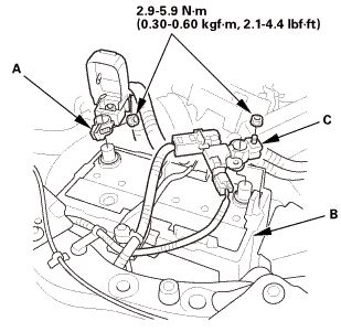 (o.2ao.sam. (o.2ao.sam.
|
|
NOTE: If the battery performs abnormally, test the battery.
|
|
1.
|
Clean the battery terminals.
|
|
2.
|
Connect the positive cable (A) to the battery (B).
|
|
NOTE: Always connect the positive side first.
|
|
3.
|
Connect the negative cable and battery sensor (C) to the battery.
|
|
4.
|
Apply multipurpose grease to the terminals to prevent corrosion.
|
|
|
|
|
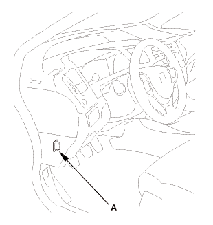
1.
|
Connect the HDS to the data link connector (DLC) (A) located
under the driver's side of the dashboard.
|
|
2.
|
Turn the ignition switch to ON (II).
|
|
3.
|
Make sure the HDS communicates with the vehicle. If it does not
communicate, go to the DLC circuit troubleshooting.
|
|
| 7. |
VSA Sensor Neutral Position - Memorization |
|
|
1.
|
Park the vehicle on a flat and level surface, with the steering
wheel in the straight ahead position.
|
|
2.
|
Select VSA ADJUSTMENT, then select ALL SENSORS with the HDS,
and follow the screen prompts.
|
|
NOTE: See the HDS Help menu for specific instructions.
|
|
| 8. |
Steering Angle Sensor Neutral Position - Clear |
|
|
1.
|
Select EPS ADJUSTMENT, then select EPS STEERING ANGLE SENSOR
VALUE CLEAR and follow the screen prompts on the HDS.
|
|
NOTE: See the HDS Help menu for specific instructions.
|
|
| 9. |
Confirm Proper SRS Operation |
|
|
Turn the ignition switch to ON (II), and check that the SRS indicator
comes on for about 6 seconds and then goes off.
|
|
728100
Removal
SRS components are located in this area. Review the SRS component locations
and the precautions and procedures before doing repairs or service.
1 ...
1.
Trunk Floor Cover
1.
Fold down the seat-back(s).
2.
...
See also:
Honda Civic Owners Manual. Power Door Mirrors
You can adjust the door mirrors when the
ignition switch is in ON *1.
Mirror position adjustment
L/R selector switch: Select the left or right
mirror. After adjusting the mirror, return the
switch to the center position.
Mirror position adjustment switch: Press
the switch left, right, u ...
 Combination Light Switch Removal, Installation, and Test
 Taillight Removal and Installation ('13-'14: 4-door except Natural Gas models)