Honda Civic Service Manual: Crankshaft and CKP Pulse Plate Removal, Installation, and Inspection (R18A9)

Removal
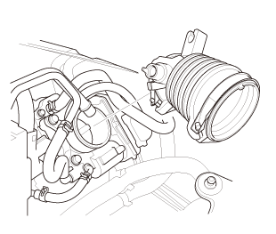
| 1. | Intake Manifold and Throttle Body Assembly (Natural Gas Model) |
|
|
|
|
|
|
|
|
|

|
|
|
|
|
|
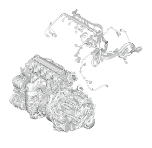
| 2. | Engine Wire Harness |
|
|
|
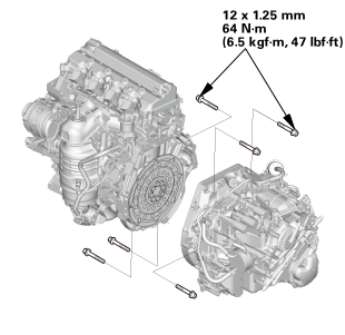
| 3. | Automatic Transmission Assembly (A/T) |
|
|
|
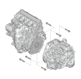
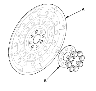
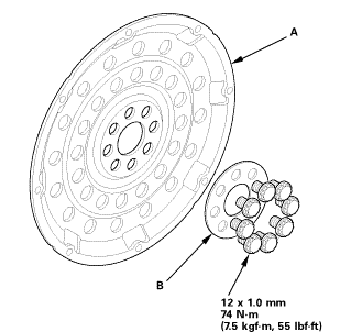
| 4. | Drive Plate Assembly |
|
|
|
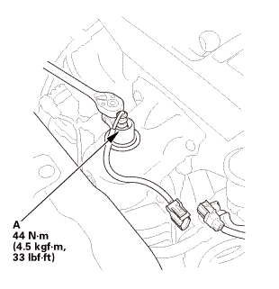
| 5. | A/F Sensor (Sensor 1) |
|
|
|
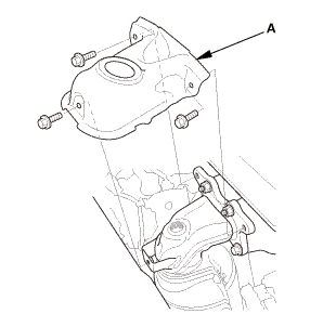
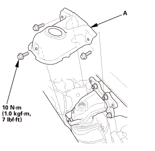
| 6. | Exhaust Chamber Cover (Natural Gas Model) |
|
|
|
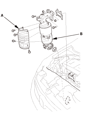
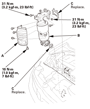
| 7. | Catalytic Converter (Natural Gas Model) |
|
|
|
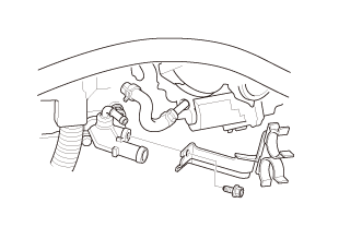
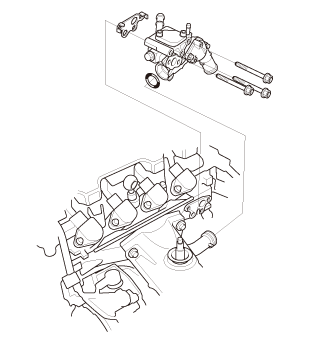
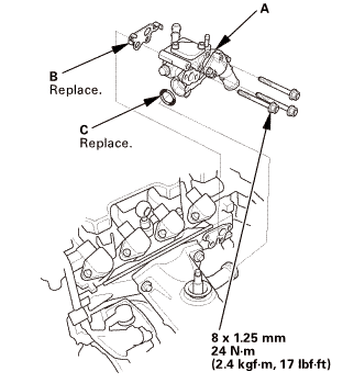
| 8. | Thermostat Housing (Natural Gas Model) |
|
|
|
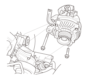
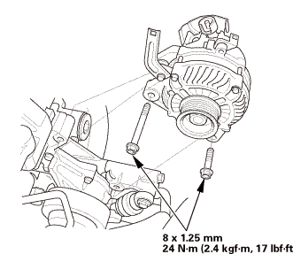
| 9. | Alternator |
|
|
|
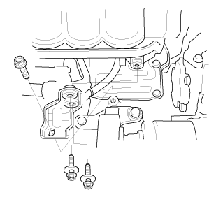
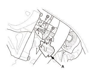
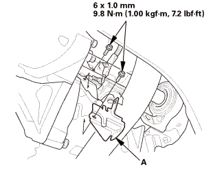
| 10. | Lower Torque Rod Bracket (A/T) |
|
|
|
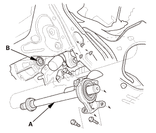
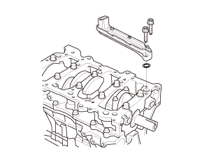
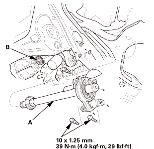
| 11. | Intermediate Shaft Assembly |
|
|
|
|
|
|
||||||
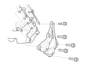
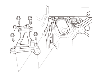
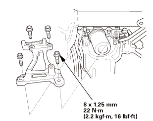
| 12. | A/C Compressor Bracket |
|
|
|
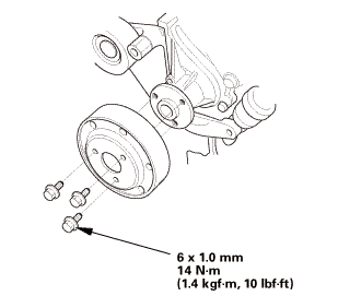
| 13. | Water Pump Pulley |
|
|
|
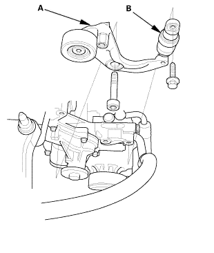
| 14. | Auto Tensioner Assembly |
|
|
|
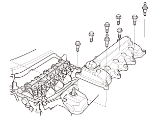
| 15. | Cylinder Head Cover and/or Packing |
|
|
|
|
|
|
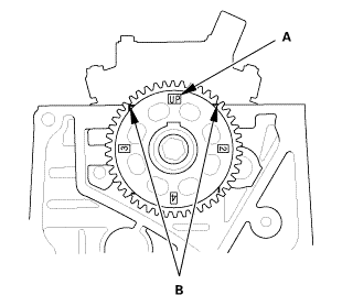
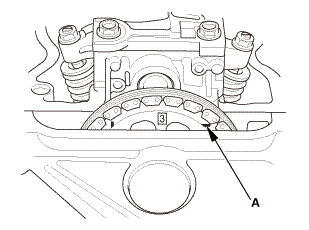
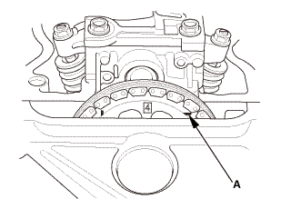
| 16. | Check The No.1 Piston at Top Dead Center (With Cam Chain Case/Oil Pump) |
|
|
|
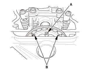
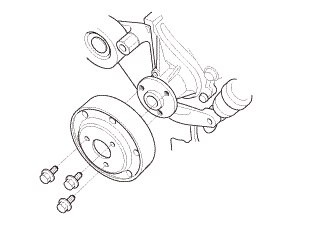
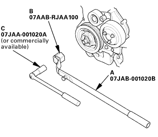
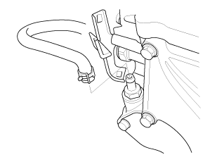
| 17. | Crankshaft Pulley |
|
|
|
 [av
[av| 18. | Engine Oil Pump Assembly |
|
|
|
|
|
|
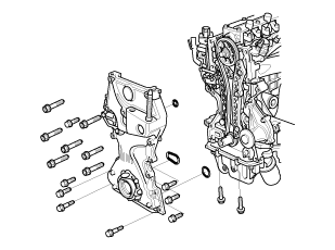
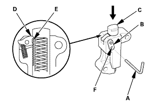
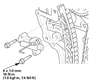
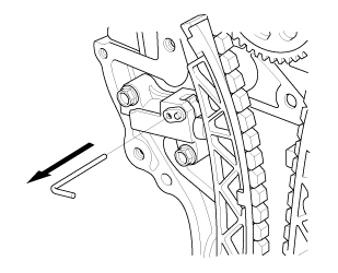
| 19. | Cam Chain Auto-Tensioner |
|
|
|
||||||||||||
|
|
|
|
|
|
||||||||||||
|
|
|
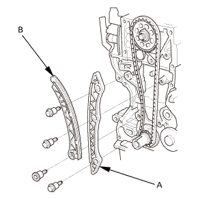
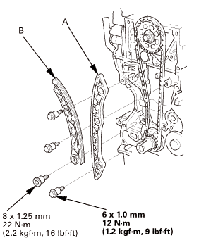
| 20. | Cam Chain |
|
|
|
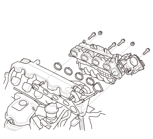
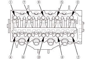
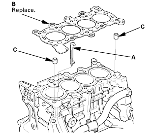
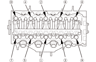
| 21. | Cylinder Head Assembly |
|
|
|
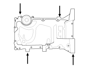
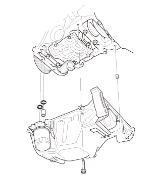
| 22. | Oil Pan Assembly |
|
|
|
|
|
|
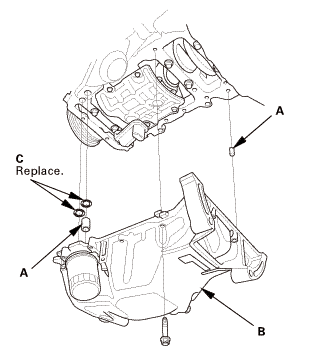
| 23. | Engine Oil Strainer |
|
|
|
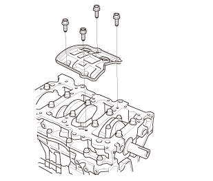
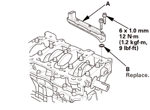
| 24. | Engine Baffle Plate |
|
|
|
| 25. | Connecting Rod Cap and The Bearing Half |
|
|
|
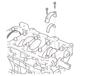
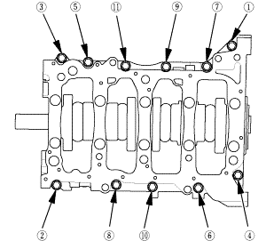
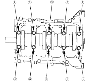
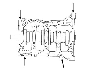
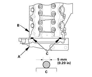
| 26. | Cylinder Lower Block Assembly |
|
|
|
|
|
|
|
|
|
|
|
|
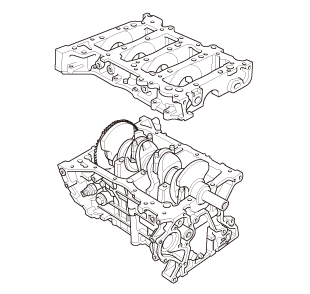
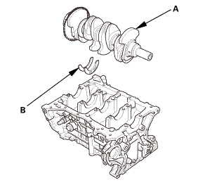
| 27. | Crankshaft |
|
|
|
| 28. | Crankshaft Oil Seal, Transmission Side |
|
|
|
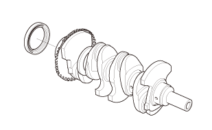
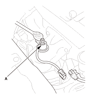
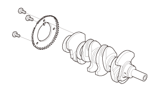
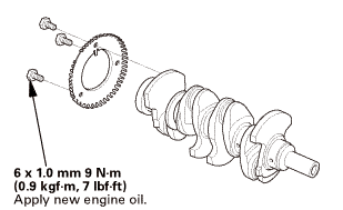
| 29. | CKP Pulse Plate |
|
|
|
 Inspection
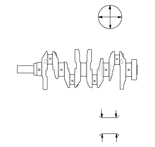
| 1. | Crankshaft - Inspection |
|
Out-of-Round and Taper |
|
1. |
Clean the crankshaft oil passages with pipe cleaners or a suitable brush. |
|
2. |
Check the keyway slot and the threaded holes. |
|
3. |
Measure the out-of-round at the middle of each rod and main journal in two places. The difference between measurements on each journal must not be more than the service limit. |
|||||||||
|
||||||||||
|
4. |
Measure the taper at the edges of each rod and the main journal. The difference between measurements on each journal must not be more than the service limit. |
|||||||||
|
||||||||||
|
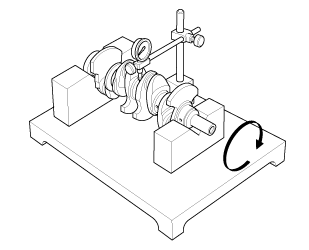
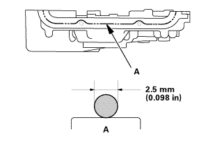
Straightness |
|
5. |
Place the V-blocks on a flat surface. |
|
6. |
Check the total runout with the crankshaft supported on V-blocks. |
|
7. |
Measure the runout on all of the main journals. Rotate the crankshaft two complete revolutions. The difference between measurements on each journal must not be more than the service limit. |
|||||||||
|
||||||||||

Installation
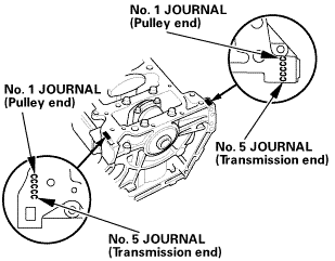
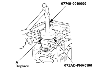
| 1. | CKP Pulse Plate |
|
|
|
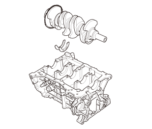
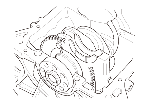
| 2. | Crankshaft |
|
|
|
||||||
|
|
|
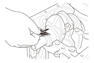
| 3. | Main Bearing Clearance Inspection |
|
|
|
||||||||||||||||||||||||||


|
|
|
||||||||||||||||||||
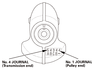
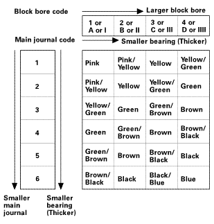
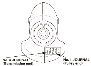
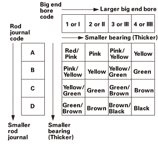
| 4. | Crankshaft Main Bearing - Selection |
|
|
|
 na.nono
|
|
|
 nojournal
|
|
|
|||||||||||||||||
 bunamvllluwgemam,inwmam;
| 5. | Cylinder Lower Block Assembly |
|
|
|
|||||||||||||||||||||||
|
|
|
|
|
|
|
|
|
|
|
|
|||||||||||||||||

| 6. | Connecting Rod Bearing Clearance Inspection |
|
|
|
|||||||||||||||||||||||||||||||||||||||||||
| 7. | Connecting Rod Bearing Selection |
|
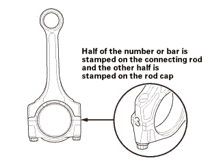
1. |
Inspect each connecting rod for cracks and heat damage. |
 redandrunisind
|
2. |
Each connecting rod has a tolerance range from 0 to 0.024 mm (0.00094 in), in 0.006 mm (0.00024 in) increments, depending on the size of its big end bore. It's then stamped with a number or bar (1, 2, 3, or 4/l, ll, lll, or llll) indicating the range. You may find any combination of numbers and bars in any engine. (Half the number or bar is stamped on the rod cap, the other half is on the connecting rod.) If you cannot read the code because of an accumulation of oil and varnish, do not scrub it with a wire brush or scraper. Clean it only with solvent or detergent. |
|||||
|
||||||
|
|
|
 (pulley
|
|
|
|||||||||||||||||
 a.ndendam,amznvllred/pink/pinkvellawpink/emwnbrawnsmnllevmd
| 8. | Connecting Rod Cap and The Bearing Half |
|
|
|
|
|
|
|||||||||
| 9. | Engine Baffle Plate |
|
|
|
| 10. | Engine Oil Strainer |
|
|
|
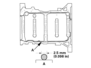
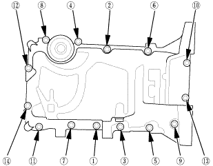
| 11. | Oil Pan Assembly |
|
|
|
|||||||||||||||||||||||
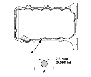 mm
mm|
|
|
|
|
|
|||||||||||||||||
| 12. | Cylinder Head Assembly |
|
|
|
|
|
|
 inmmam
|
|
|
|
|
|
||||||
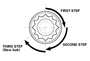 secounstep
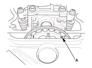
| 13. | Set The No.1 Piston at Top Dead Center (Without Cam Chain Case/Oil Pump) |
|
|
|
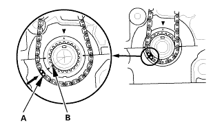
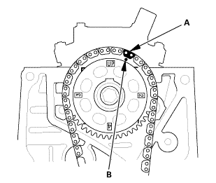
| 14. | Cam Chain |
|
|
|
|
|
|
|
|
|
 ...,is(1.2
| 15. | Cam Chain Auto-Tensioner |
|
|
|
||||||
|
|
|
 nokvf-in.
|
|
|
| 16. | Engine Oil Pump Assembly |
|
|
|
||||||||||||||||||||||||||
|
|
|
||||||||||||||
|
|
|
||||||||||||||||||||||||||||||
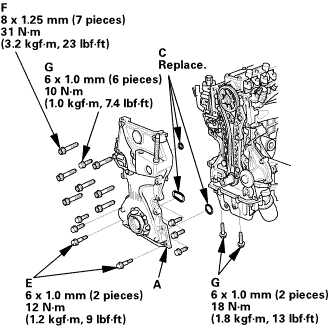 25mm(7(32k1n1omm12
| 17. | Crankshaft Oil Seal, Transmission side |
|
|
|
|
|
|
||||||||||
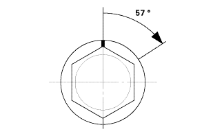
| 18. | Crankshaft Pulley |
|
|
|
|
|
|
|
|
|
|||||||||||||
 o7jaanmo2oa
|
|
|
||||||||||
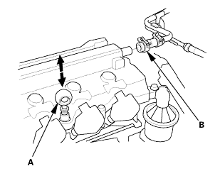
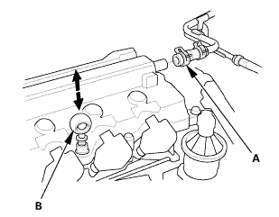
| 19. | Valve Clearance Adjustment |
|
|
|

|
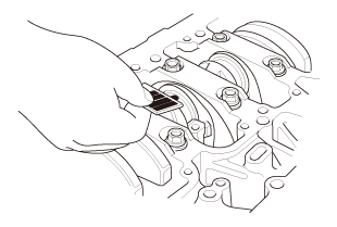
2. |
Select the correct feeler gauge for the valve clearance you are going to check. |
|||||||||
|
||||||||||
 no!
no!
|
|
|
|
|
|
|||||||||||||||
|
|
|
|
|
|
|
|
|
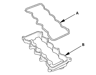
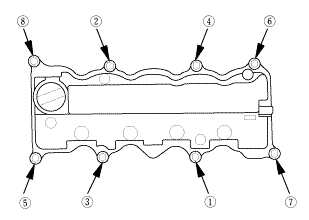
| 20. | Cylinder Head Cover and/or Packing |
|
|
|
|||||||||||||||
|
|
|
||||||||||||||||||||
|
|
|
||||||||||||||||||||
|
|
|
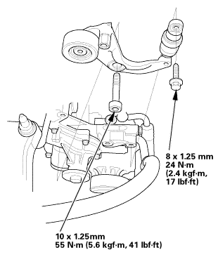
| 21. | Auto Tensioner Assembly |
|
|
|
 inl.25mmssn-m
| 22. | Water Pump Pulley |
|
|
|
| 23. | A/C Compressor Bracket |
|
|
|
| 24. | Intermediate Shaft Assembly |
|
|
|
||||||
 inmmn-mu.o
|
|
|
 mms.
mms.| 25. | Lower Torque Rod Bracket (A/T) |
|
|
|
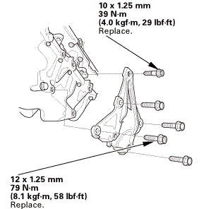 u.z5mm75n-mmm
| 26. | Alternator |
|
|
|
| 27. | Thermostat Housing (Natural Gas Model) |
|
|
|
 imm
imm| 28. | Catalytic Converter (Natural Gas Model) |
|
|
|
 :1mm.....
| 29. | Exhaust Chamber Cover (Natural Gas Model) |
|
|
|
| 30. | A/F Sensor (Sensor 1) |
|
|
|
| 31. | Drive Plate Assembly |
|
|
|
 55
55| 32. | Automatic Transmission Assembly (A/T) |
|
|
|
 usmmn-mlbml)
| 33. | Engine Wire Harness |
|
|
|
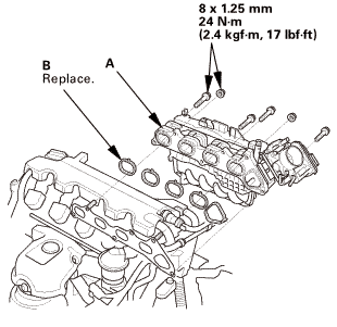
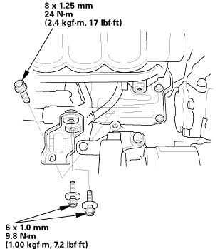
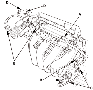
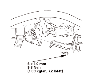
| 34. | Intake Manifold and Throttle Body Assembly (Natural Gas Model) |
|
|
|
|
|
|
|
|
|
|
|
|
|
|
|
 CMP Sensor B Removal and Installation (K24Z7)
1211X7
Removal
1.
EVAP Canister Purge Valve and Bracket
1.
Remove the air cleaner upper cover (A).
...
 ECT Sensor 2 Removal and Installation (K24Z7)
1201D5 RADIATOR
1.
Radiator Cap
1.
Wait until the engine is cool, then carefully remove the radiator
cap.
...
See also:
Honda Civic Owners Manual. How to Refuel
Your fuel tank is not equipped with a fuel filler cap. You can insert the
filler nozzle
directly into the filler neck. The tank seals itself again when you pull out the
filler
nozzle.
Stop your vehicle with the service station
pump on the left side of the vehicle in the
rear.
&nb ...
