|

|
Use this procedure when you need to update the VSA modulator-control
unit at any time.
|
|
|
|
Make sure the HDS/iN workstation has the latest software
version.
|
|
|
|
Before you update the VSA modulator-control unit, make
sure the battery in the vehicle is fully charged, and connect
a jumper to the battery (not a battery charger) to maintain
system voltage.
|
|
|
|
Never turn the ignition switch to LOCK (0) or ACCESSORY
(I) during the update. If there is a problem with the update,
leave the ignition switch ON (II).
|
|
|
|
To prevent VSA modulator-control unit damage, do not
operate anything electrical (headlights, audio system, brakes,
A/C, power windows, door locks, etc.) during the update.
|
|
|
|
To ensure the latest program is installed, do a VSA modulator-control
unit update whenever the VSA modulator-control unit is substituted
or replaced.
|
|
|
|
You cannot update a VSA modulator-control unit with a
program it already has. It will only accept a new program.
|
|
|
|
High temperature in the engine compartment might cause
the VSA modulator-control unit to become too hot to run
the update. If the engine has been running before this procedure,
open the hood and cool the engine compartment.
|
|
|
|
If you need to diagnose the Honda interface module (HIM)
because the HIM's red (#3) light came on or was flashing
during the update, leave the ignition switch in ON (II)
when you disconnect the HIM from the data link connector
(DLC). This will prevent VSA modulator-control unit damage.
|
|
|
|
DTCs stored in memory are cleared when the VSA modulator-control
unit is updated.
|
|

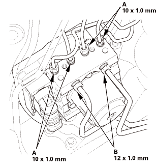

 !5nm
!5nm
 in-.omm..ismm(15111mm!0xl.0mmmm15mmkvl-m,mm(15

 sznuzucz
 m.uimm
 sun.(on
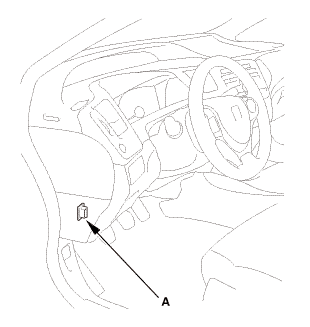

 VSA Off Switch Removal and Installation (Except K24Z7)