Honda Civic manuals

Honda Civic Service Manual: Valve Guide Replacement (R18A9)

Honda Civic Service Manual / Powertrain / Engine / Valvetrain / Valve Guide Replacement (R18A9)

1. Fuel Pressure - Relieving (Between the engine and the manual shut-off valve) (Natural Gas Model)


Compressed natural gas is flammable and highly explosive. You could be killed or seriously injured if leaking natural gas is ignited.
Stop the engine, and keep heat, sparks, and flames away.


This procedure should be done outside in a well-ventilated area or in a properly equipped CNG shop.


This procedure will allow you to safely work on any part of the fuel system downstream of the manual shut-off valve, such as fuel pressure regulator P1 or the fuel injectors.


1.

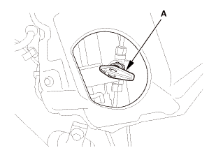
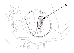
Close the manual shut-off valve (A).


2.

Start the engine, and let it idle.


3.

After a few minutes, the engine will stall.


4.

Turn the ignition switch to LOCK (0).


2. Vehicle Lift

1.

Raise the vehicle on a lift, and make sure it is securely supported.


3. Tire and Wheel-Removal, Front Right

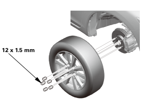
12x1mm
1.

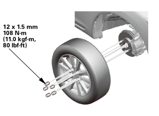
Remove the right front wheel.


4. Battery Terminal - Disconnection


1.

Make sure the ignition switch is in LOCK (0), or the vehicle ignition in the OFF mode.


2.

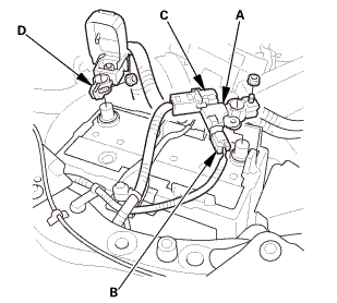
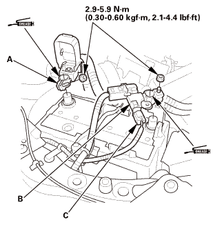
Disconnect and isolate the negative cable with the battery sensor (A) from the battery.


NOTE:

Always disconnect the negative side first.

To protect the battery sensor connector (B) from damage, do not hold it when removing the negative terminal.

Do not disconnect the battery sensor from the negative terminal (C).


3.

Disconnect the positive cable (D) from the battery.


5. Battery

1.

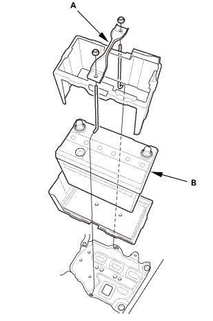
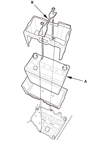
Remove the battery setting plate (A) and the battery (B).


6. Engine Cover

1.

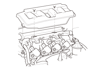
Remove the engine cover.


7. Radiator Cap

1.

Wait until the engine is cool, then carefully remove the radiator cap.


8. Radiator Coolant - Replacement

1.

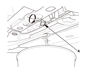
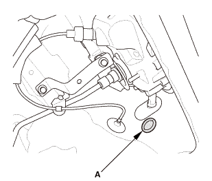
Loosen the drain plug (A), and drain the coolant.


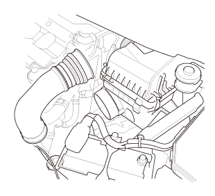
9. Intake Air Pipe

1.

Remove the intake air pipe.


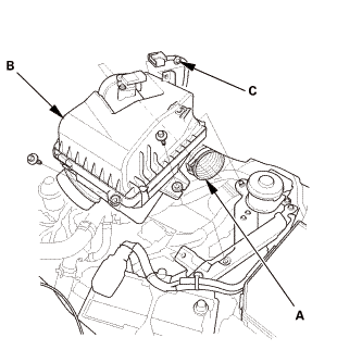
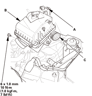
10. Air Cleaner


1.

Disconnect the intake air duct (A).


2.

Remove the air cleaner (B).


3.

Remove the harness clamp (C).


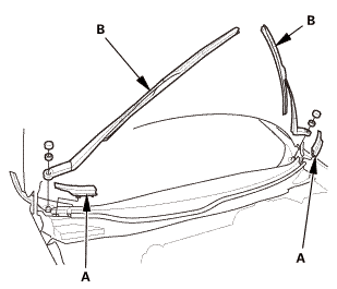
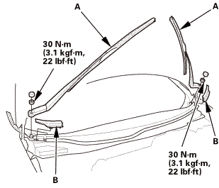
11. Wiper Arm Assembly


NOTE: Set the wiper arms to the auto-stop position before removal.


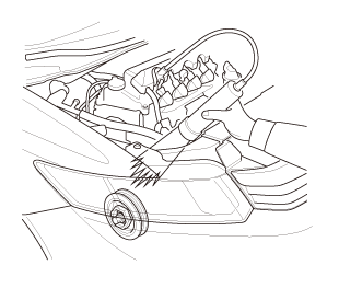
1.

Remove the cowl top wiper covers (A).


2.

Remove the wiper arms (B).


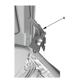
12. Both Side Cowl Covers


1.

Remove the side cowl cover (A).


2.

The left side is shown; repeat on the right side.


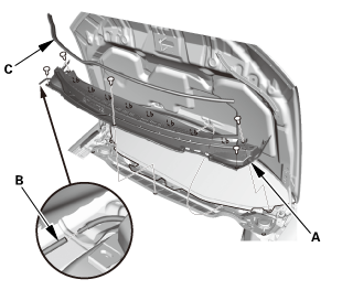
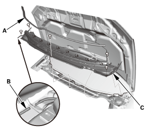
13. Center Cowl Cover


1.

Remove the center cowl cover (A).


2.

Disconnect the windshield washer tube (B).


3.

If necessary, remove the hood rear seal (C).


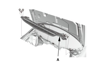
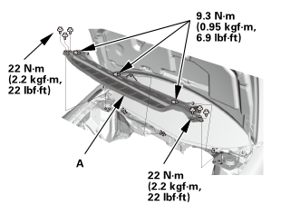
14. Under Cowl Panel

1.

Remove the under cowl panel (A).


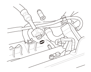
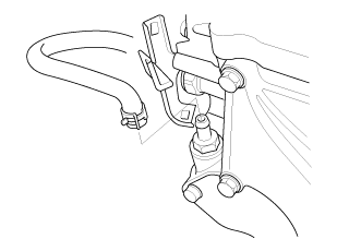
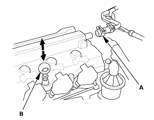
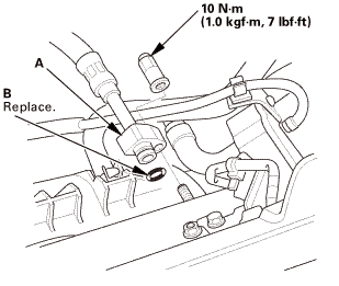
15. Fuel Feed Hose (Natural Gas Model)

1.

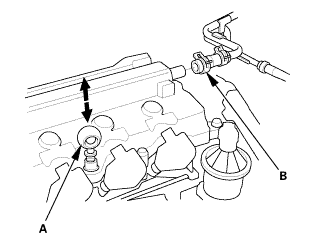
Disconnect the fuel feed hose.


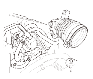
16. Intake Air Duct

1.

Remove the intake air duct.


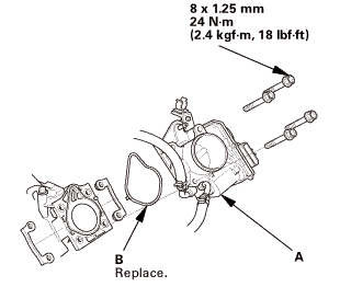
17. Throttle Body - Remove (Natural Gas Model)

1.

Remove the throttle body without disconnecting the hoses.


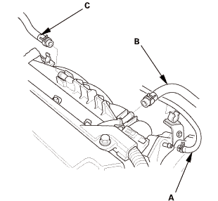
18. Intake Manifold Assembly (Natural Gas Model)

1.

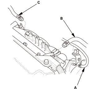
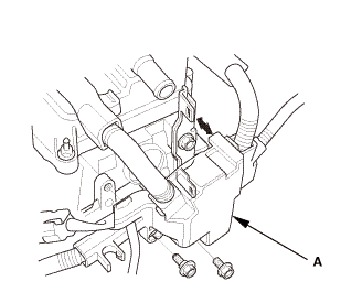
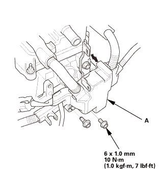
Disconnect the EVAP canister hose (A), the brake booster vacuum hose (B), and the PCV hose (C).


2.

Remove the heater hose clamp bracket.


3.

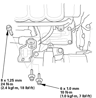
Remove the intake manifold bracket.


4.

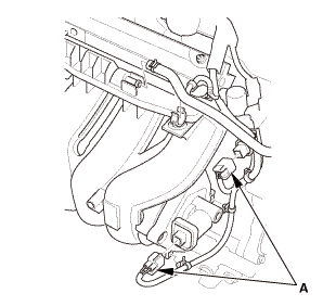
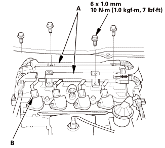
Disconnect the connectors (A).


5.

Remove the harness clamps.


6.

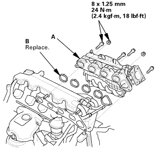
Remove the intake manifold assembly.


19. Cylinder Head Peripheral Assembly


1.

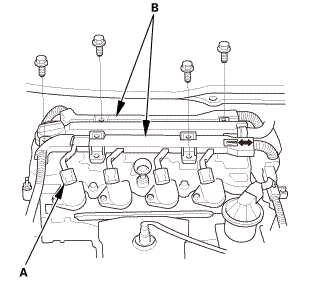
Disconnect the connectors (A).


2.

Remove the harness holders (B).


3.

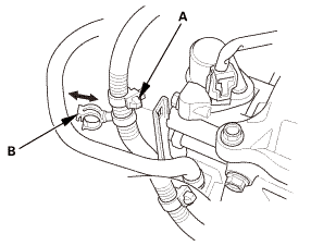
Remove the harness clamp (A).


4.

Disconnect the PCV hose from the clamp (B).


5.

Remove the harness holder (A) from the cylinder head.


6.

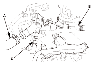
Disconnect the upper radiator hose (A), the heater hose (B), and the water bypass hose (C).


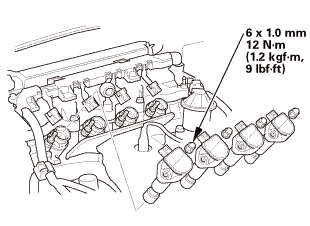
20. Ignition Coil

1.

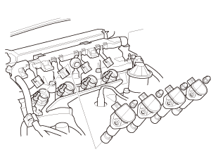
Remove the ignition coils.


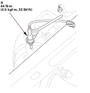
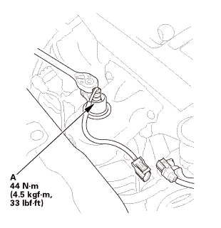
21. A/F Sensor (Sensor 1)


1.

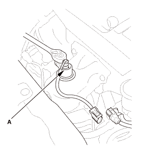
Disconnect the connector.


2.

Remove the A/F sensor (A).


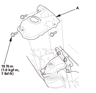
22. Exhaust Chamber Cover (Natural Gas Model)

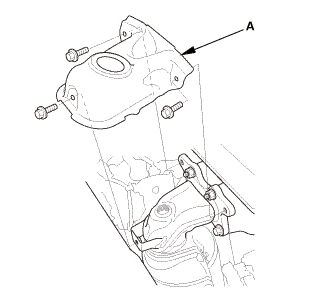
1.

Remove the exhaust chamber cover (A).


23. Splash Shield

1.

Remove the splash shield (A).


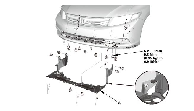
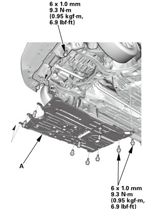
24. Engine Undercover

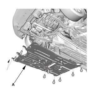
1.

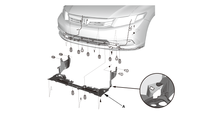
Remove the engine undercover (A).


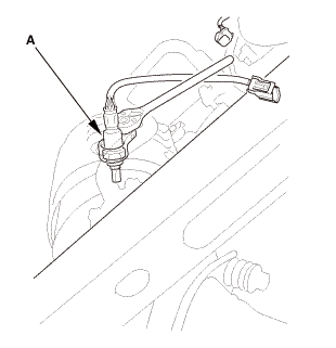
25. Secondary HO2S


1.

Disconnect the connector.


2.

Remove secondary HO2S (A).


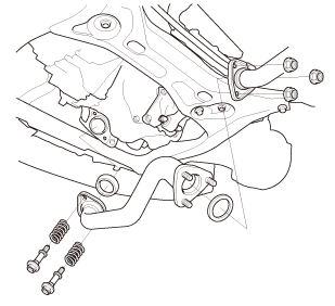
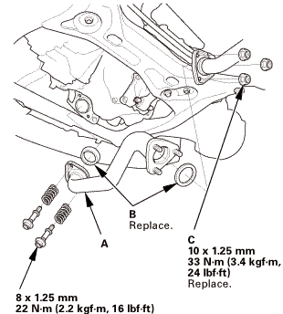
26. Exhaust Pipe A (Except CVT)

1.

Remove exhaust pipe A.


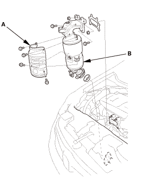
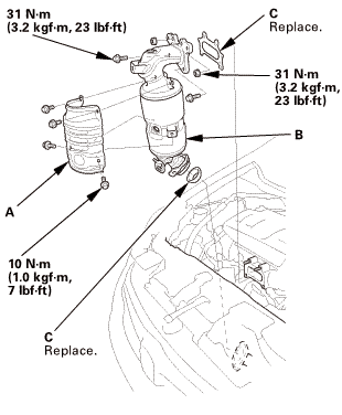
27. Catalytic Converter (Natural Gas Model)


1.

Remove the catalytic converter (A).


2.

Remove the catalytic conveter cover (B).


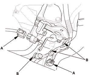
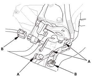
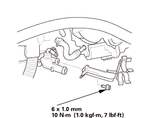
28. Thermostat Housing Peripheral Assembly (Natural Gas Model)


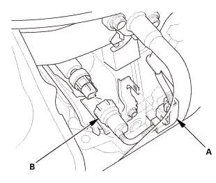
1.

Disconnect the connectors (A).


2.

Remove the harness clamps (B).


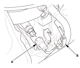
3.

Disconnect the connector (A).


4.

Remove the harness clamp (B).


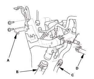
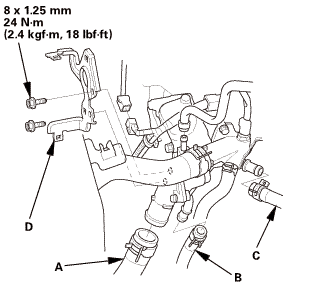
5.

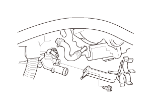
Remove the harness bracket (A).


6.

Disconnect the lower radiator hose (B), the water bypass hose (C), and the heater hose (D).


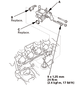
29. Thermostat Housing (Natural Gas Model)

1.

Remove the thermostat housing.


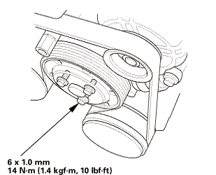
30. Water Pump Pulley Mounting Bolt - Loosen

1.

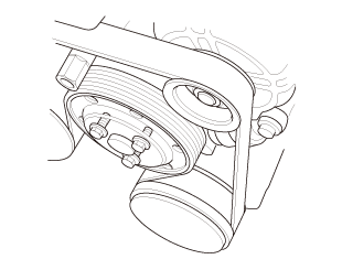
Loosen the water pump pulley mounting bolts.


31. Drive Belt


1.

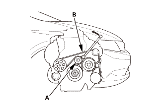
Move the auto-tensioner (A) counterclockwise to relieve tension from the drive belt (B).


2.

Remove the drive belt.


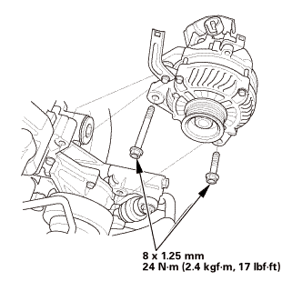
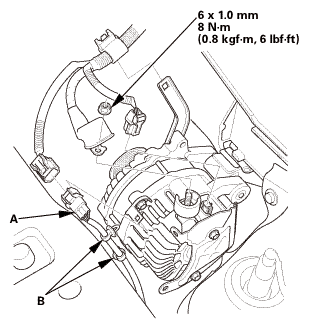
32. Alternator


1.

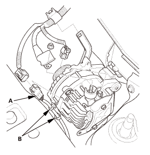
Disconnect the connector and the cable.


2.

Remove the harness connector (A) and the harness clamps (B).


3.

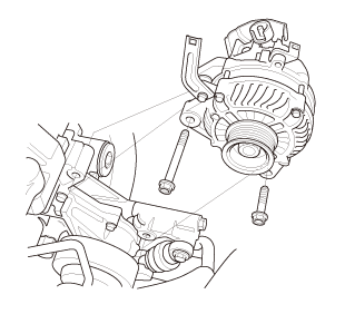
Remove the alternator.


33. Water Pump Pulley

1.

Remove the water pump pulley.


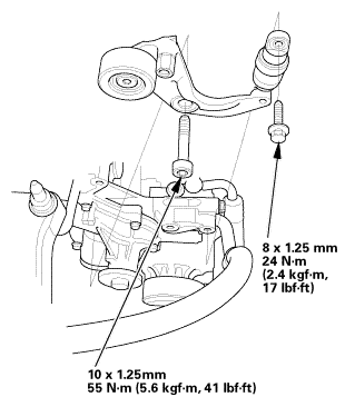
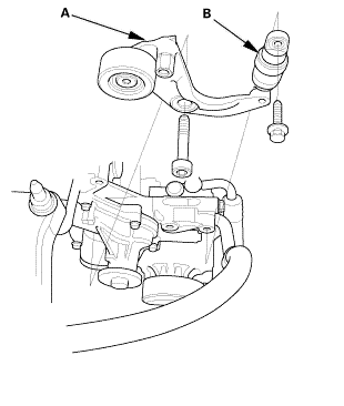
34. Auto Tensioner Assembly


1.

Remove the drive belt auto-tensioner (A).


2.

Check for oil leaks from the drive belt auto-tensioner damper (B) and check for damage to the damper rubber.


35. Cylinder Head Cover and/or Packing


1.

Remove the dipstick (A).


2.

Disconnect the breather hose (B).


3.

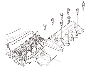
Remove the cylinder head cover.


36. Check The No.1 Piston at Top Dead Center (With Cam Chain Case/Oil Pump)

1.

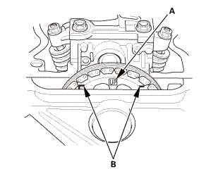
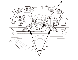
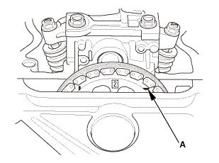
Set the No. 1 piston at top dead center (TDC). The ‘‘UP’’ mark (A) on the camshaft sprocket should be at the top, and the TDC grooves (B) on the camshaft sprocket should line up with the top edge of the head.


37. Crankshaft Pulley

[av


1.

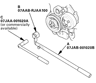
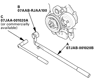
Hold the pulley with the holder handle (A) and the crankshaft pulley holder (B).


2.

Remove the bolt with a socket, 19 mm (C) and a breaker bar.
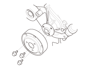

3.

Remove the crankshaft pulley.


38. Engine Jack Support (State Of A Low Vehicle)

1.

Lift and support the engine with a jack and a wood block under the oil pan.


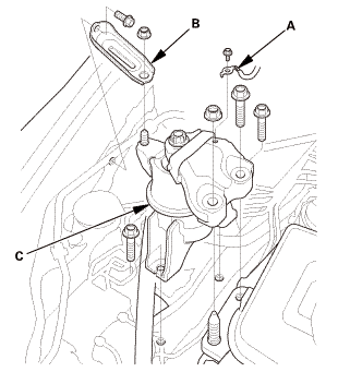
39. Mounting Bracket, Engine Side

1.

Remove the ground cable (A), the side engine mount bracket (B), and the side engine mount (C).


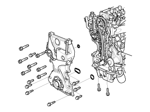
40. Engine Oil Pump Assembly

1.

Disconnect the PCV hose.


2.

Remove the oil pump.


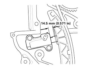
41. Cam Chain Auto-Tensioner
1.

Measure the tensioner rod length between the tensioner body and bottom of the flat surface section on the tensioner rod. If the length is more than the service limit, replace the cam chain.


Tensioner Rod Length

Service Limit:

14.5 mm (0.571 in)


2.

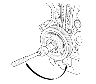
Loosely install the crankshaft pulley.


3.

Turn the crankshaft counterclockwise to compress the auto-tensioner.


4.

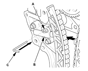
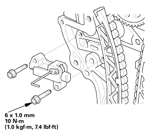
Rotate the crankshaft counterclockwise to align the holes on the lock (A) and the auto-tensioner (B).


5.

Insert a 1.0 mm (1/32 in) diameter pin (C) into the holes.


6.

Turn the crankshaft clockwise to secure the pin.


NOTE: If the holes in the lock and the auto-tensioner do not align, continue to rotating the crankshaft counterclockwise until the holes align, then install the pin.


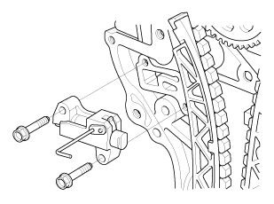
7.

Remove the cam chain auto-tensioner.


8.

Remove the crankshaft pulley.


42. Cam Chain


1.

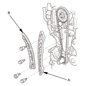
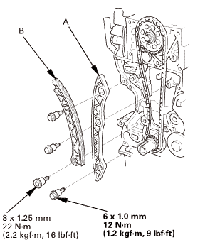
Remove the cam chain guide (A) and the cam chain tensioner arm (B).


2.

Remove the cam chain.


43. Cylinder Head Assembly


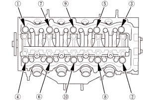
1.

Remove the cylinder head bolts. To prevent warpage, loosen the bolts in sequence, 1/3 turn at a time, repeat the sequence until all bolts are loosened.


2.

Remove the cylinder head.


44. Rocker Arm Assembly

1.

Loosen the locknuts and the adjusting screws (A).


2.

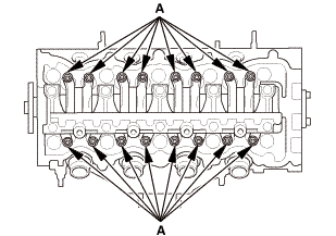
Remove the lost motion holder bolts. To prevent damaging the lost motion holder and the rocker shaft.


3.

loosen the bolts, in sequence, two turns at a time.


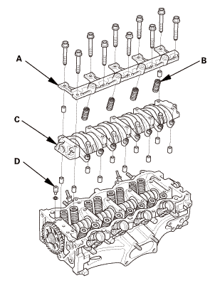
4.

Remove the lost motion holder (A) and the lost motion assemblies (B).


5.

Remove the rocker arm assembly (C).


6.

Remove the oil control orifice (D).


45. Camshaft Sprocket


1.

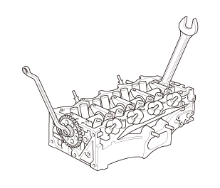
Hold the camshaft with a 27 mm open-end wrench.


2.

loosen the camshaft sprocket mounting bolt.


3.

Remove the camshaft sprocket.


46. Camshaft


1.

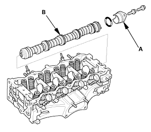
Remove the camshaft thrust cover (A).


2.

Pull out the camshaft (B).


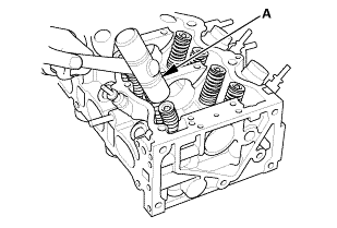
47. Valve Spring

1.

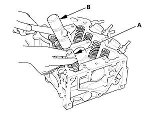
Using an appropriate-sized socket (A) and a plastic mallet (B), lightly tap the spring retainer to loosen the valve cotters.


o77s7n


2.

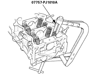
Install the valve spring compressor attachment and the valve spring compressor.


3.

Compress the valve spring and remove the valve cotters.


4.

Remove the valve spring compressor and the valve spring compressor attachment.


5.

Remove the spring retainer, the valve spring, and the valve.


48. Valve Seal

1.

Install the valve guide seal remover (A).


2.

Remove the valve seal.


49. Valve Guide

mmmmmlmmam


1.

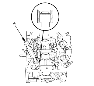
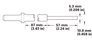
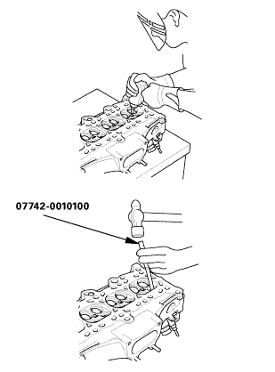
As illustrated, use a commercially available air-impact valve guide driver (A) modified to fit the diameter of the valve guides. In most cases, the same procedure can be done using the valve guide driver, 5.35 x 9.7 mm and a conventional hammer.


2.

Select the proper replacement guides, and chill them in the freezer section of a refrigerator for at least an hour.


3.

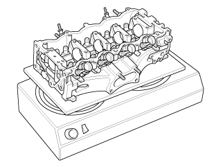
Use a hot plate or oven to evenly heat the cylinder head to 300 °F (150 °C). Monitor the temperature with a cooking thermometer. Do not get the head hotter than 300 °F (150 °C); excessive heat may loosen the valve seats.


4.

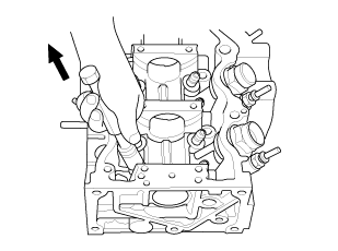
Working from the camshaft side, use the driver and an air hammer to drive the guide about 2 mm (0.08 in) towards the combustion chamber. This will knock off some of the carbon and make removal easier. Hold the air hammer directly in line with the valve guide to prevent damaging the driver. Wear safety goggles or a face shield.


5.

Turn the head over, and drive the guide out toward the camshaft side of the head.


6.

If a valve guide will not move, drill it out with an 8mm (5/16 in) drill bit, then try again.


NOTE: Drill guides only in extreme cases; you could damage the cylinder head if the guide breaks.


1. Valve Guide


1.

Take out the new guide(s) from the freezer, one at a time, as you need them.


2.

Apply a thin coat of new engine oil to the outside of the new valve guide.


3.

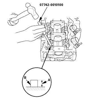
Install the guide from the camshaft side of the head; use the valve guide driver to drive the guide into the specified installed height (A) of the guide (B). If you have all eight guides to do, you may have to reheat the head.


Valve Guide Installed Height:

18.25-18.75 mm (0.7185-0.7382 in)


4.

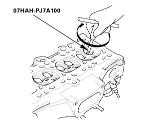
Coat both the valve guide reamer, 5.5 mm and the valve guide with cutting oil.


5.

Rotate the valve guide reamer clockwise the full length of the valve guide bore.


6.

Continue to rotate the reamer clockwise while drawing it from the bore.


7.

Thoroughly wash the guide in detergent and water to remove any cutting residue.


2. Valve Seal

1.

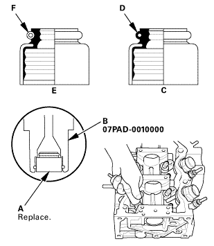
Install the new valve seals (A) using the 5.5 mm side of the stem seal driver (B).


NOTE: The exhaust valve seal (C) has a black spring (D), and the intake valve seal (E) has a white spring (F), they are not interchangeable.


3. Valve Spring

o77s7n


1.

Install the valve spring and the spring retainer. Place the end of the valve spring with the closely wound coils toward the cylinder head.


2.

Install the valve spring compressor attachment and the valve spring compressor.


3.

Compress the spring and install the valve cotters.


4.

Remove the valve spring compressor and the valve spring compressor attachment.


5.

Lightly tap the end of each valve stem two or three times with a plastic mallet (A) to ensure proper seating of the valve and the valve cotters. Tap the valve stem only along its axis so you do not bend the stem.


NOTE: Be sure to raise the head off the work bench so the valve is not possibly damaged.


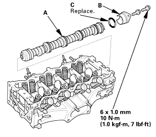
4. Camshaft

tommnomm


1.

Install the camshaft (A).


2.

Install the camshaft thrust cover (B) with a new O-ring (C).


5. Camshaft Sprocket


1.

Install the camshaft sprocket.


2.

Apply new engine oil to the threads of the camshaft sprocket mounting bolt.


3.

Install the camshaft sprocket mounting bolt.


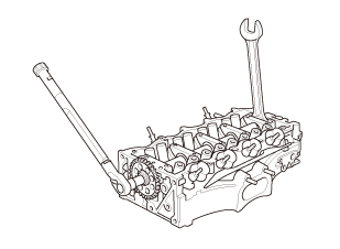
4.

Hold the camshaft with a 27 mm open-end wrench.


5.

Tighten the camshaft sprocket mounting bolt.


Specified Torque:

10 x 1.25 mm 57 N·m (5.8 kgf·m, 42 lbf·ft)


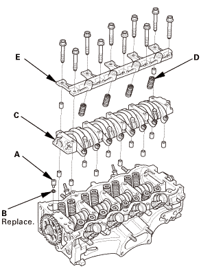
6. Rocker Arm Assembly


1.

If the rocker arm assembly is disassembled, reassemble the rocker arm assembly.


2.

Install the oil control orifice (A) with a new O-ring (B).


3.

Install the rocker arm assembly (C).


4.

Install the lost motion assembles (D) and the lost motion holder (E).


NOTE: Apply new engine oil to the lost motion assembly.


5.

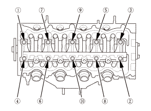
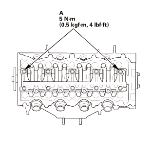
Tighten the two lost motion holder bolts (A).


6.

Tighten each bolts two turns at a time in sequence.


Specified Torque:

6 x 1.0 mm 15 N·m (1.5 kgf·m, 11 lbf·ft)


7. Cylinder Head Assembly


1.

Clean the cylinder head and the engine block surface.


2.

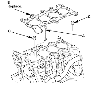
Install a new coolant separator (A) in the engine block whenever the engine block is replaced.


3.

Install the new cylinder head gasket (B) and the dowel pins (C) on the engine block. Always use a new cylinder head gasket.


4.

Install the cylinder head on the engine block.


inmmam


5.

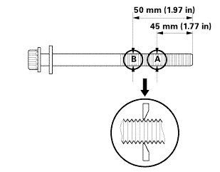
Measure the diameter of each cylinder head bolt at point A and point B.


6.

If either diameter is less than 10.6 mm (0.417 in), replace the cylinder head bolt.


7.

Apply new engine oil to the threads and under the bolt heads of all cylinder head bolts.


8.

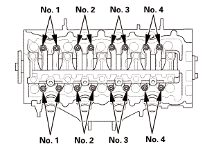
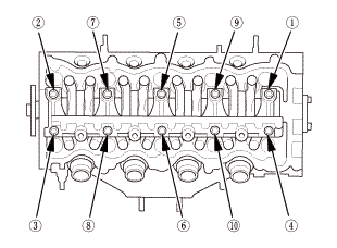
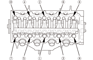
Torque the cylinder head bolts in sequence to 40 N·m (4.1 kgf·m, 30 lbf·ft). Use a beam-type torque wrench. When using a preset click-type torque wrench, be sure to tighten slowly and do not overtighten. If a bolt makes any noise while you are torquing it, loosen the bolt and retighten it from the first step.


secounstep

9.

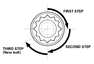
After torquing, tighten all cylinder head bolts in two steps (90 ° per step using the sequence shown in step 8). If you are using a new cylinder head bolt, tighten the bolt an extra 60 °.


NOTE: Remove the cylinder head bolt if you tightened it beyond the specified angle, and go back to step 5 of the procedure. Do not loosen it back to the specified angle.


8. Cam Chain

1.

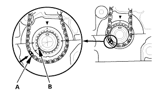
Install the cam chain on the crankshaft sprocket with the colored piece (A) aligned with the mark (B) on the crankshaft sprocket.


2.

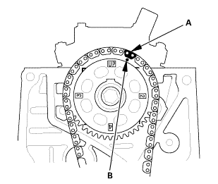
Install the cam chain on the camshaft sprocket with the colored link plate (A) aligned with the mark (B) on the camshaft sprocket.


...,is(1.2

3.

Install the cam chain guide (A) and the cam chain tensioner arm (B).


9. Cam Chain Auto-Tensioner

1.

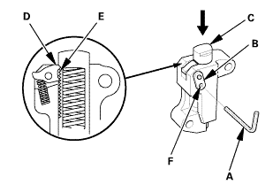
Compress the cam chain auto-tensioner when replacing the cam chain. Remove the pin (A) from the auto-tensioner that was installed during removal. Turn the plate (B) counterclockwise, to release the lock, then press the rod (C), and set the first cam (D) to the first edge of the rack (E). Insert the 1.0 mm (1/32 in) diameter pin back into the holes (F).


NOTE: If the chain tensioner is not set up as described, the tensioner will be damaged.


nokvf-in.

2.

Install the cam chain auto-tensioner.


3.

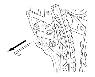
Remove the pin from the cam chain auto-tensioner.


10. Engine Oil Pump Assembly


1.

Check the oil pump oil seal for damage. If the oil seal is damaged, replace the oil seal.


2.

Remove all of the old liquid gasket from the oil pump mating surfaces, the bolts, and the bolt holes.


3.

Clean and dry the oil pump mating surfaces.


4.

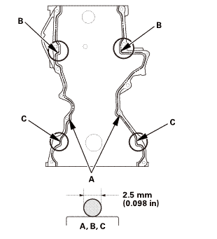
Apply liquid gasket (P/N 08718-0004 or 08718-0009) to the engine block mating surface of the oil pump, and to the inside edge of the threaded bolt holes. Install the component within 5 minutes of applying the liquid gasket.


NOTE:

Apply a 2.5 mm (0.098 in) diameter bead of liquid gasket along the broken line (A), (B), and (C).

If too much time has passed after applying the liquid gasket, remove the old liquid gasket and residue, then reapply new liquid gasket.


5.

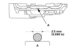
Apply liquid gasket (P/N 08718-0004 or 08718-0009) to the oil pan mating surface of the oil pump, and to the inside edge of the threaded bolt holes. Install the component within 5 minutes of applying the liquid gasket.


Apply a 2.5 mm (0.098 in) diameter bead of liquid gasket along the broken line (A).

If too much time has passed after applying the liquid gasket, remove the old liquid gasket and residue, then reapply new liquid gasket.


25mm(7(32k1n1omm12


6.

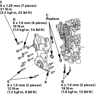
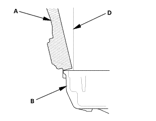
Set the edge of the oil pump (A) on the edge of the oil pan (B) with new O-rings (C).


7.

Install the oil pump on the engine block (D).


8.

Loosely install the dowel bolts (E), then tighten the 8mmbolts (F), the 6 mm bolts (G) and the dowel bolts.


9.

Wipe off the excess liquid gasket on the oil pan and oil pump mating surface.


NOTE:

When installing the oil pump, do not slide the bottom surface onto the oil pan mounting surface.

Wait at least 30 minutes before filling the engine with oil.

Do not run the engine within 3 hours after installing the oil pump.


11. Mounting Bracket, Engine Side

125mmnminm.:125mm


1.

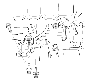
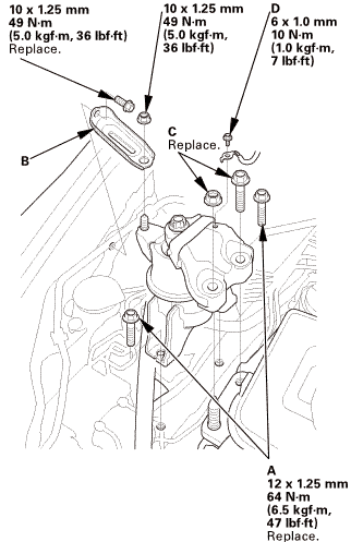
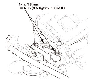
Install the new side engine mount mounting bolts (A) and the side engine mount bracket (B) using a nut and a new bolt, then loosely install the new side engine mount bracket mounting bolts and nut (C).


2.

Install the ground cable (D).


12. Engine Jack Support (State Of A Low Vehicle)

1.

Remove the jack and the wood block.


13. Transmission Mount Bracket Mounting Bolt - Loosen

M/T


A/T

1.

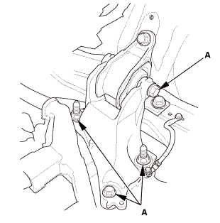
Loosen the transmission mount bracket mounting bolt and nuts (A).


14. Lower Torque Rod - Loosen

1.

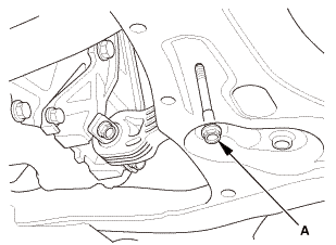
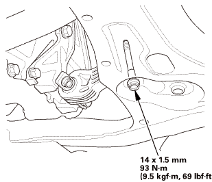
Loosen the lower torque rod mounting bolt (A).


15. Side Engine Mount - Tighten

nxl.mm

1.

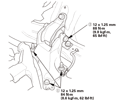
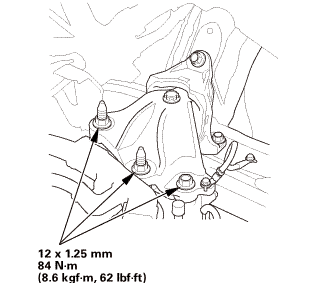
Tighten the side engine mount bracket mounting bolt and nut.


16. Transmission Mount Bracket Mounting Bolt - Tighten

1.

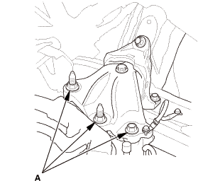
Tighten the transmission mount bracket mounting bolt and nuts.

M/T

i2mm


A/T

nz


17. Lower Torque Rod Mounting Bolt - Tighten

1.

Tighten the lower torque rod mounting bolt.


18. Crankshaft Pulley


1.

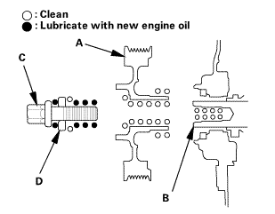
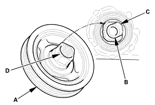
Clean the crankshaft pulley (A), the crankshaft (B), the bolt (C), and the washer (D).


2.

Lubricate with new engine oil as shown.


3.

Install the crankshaft pulley (A) onto the crankshaft (B) by aligning the flat sides (C) of the pulley with the flat sides (D) of the inner oil pump gear.


o7jaanmo2oa


When a new crankshaft or a new pulley bolt is installed


4.

Hold the pulley with the holder handle (A) and crankshaft pulley holder (B), torque the bolt to 180 N·m (18.4 kgf·m, 133 lbf·ft) with a torque wrench and a socket (C), then remove the bolt.


5.

Torque the bolt to 50 N·m (5.1 kgf·m, 37 lbf·ft) with a torque wrench and a socket.


NOTE: Tighten the crankshaft pulley bolt. Do not use an impact wrench.


6.

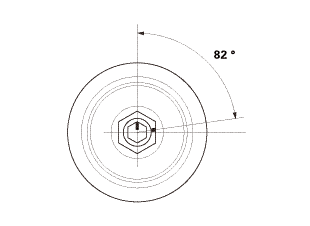
Tighten the bolt an additional 82 °.


o7jaanmo2oa


When the crankshaft or the pulley bolt is reused


7.

Hold the pulley with the holder handle (A) and crankshaft pulley holder (B), then torque the bolt to 70 N·m (7.1 kgf·m, 52 lbf·ft) with a torque wrench and a socket (C).


NOTE: Tighten the crankshaft pulley bolt. Do not use an impact wrench.


8.

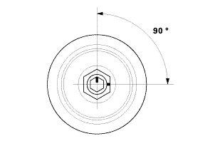
Tighten the bolt an additional 90 °.


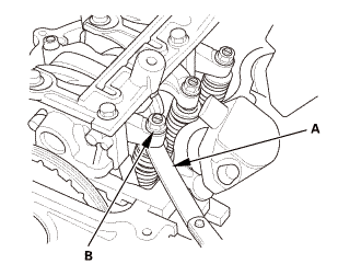
19. Valve Clearance Adjustment

1.

Set the No. 1 piston at top dead center (TDC). The ‘‘UP’’ mark (A) on the camshaft sprocket should be at the top, and the TDC grooves (B) on the camshaft sprocket should line up with the top edge of the head.


2.

Select the correct feeler gauge for the valve clearance you are going to check.


Valve Clearance

Intake:

0.18-0.22 mm (0.008-0.008 in)

Exhaust:

0.23-0.27 mm (0.010-0.010 in)

no!


3.

Insert the feeler gauge (A) between the adjusting screw (B) and the end of the valve stem on the No. 1 cylinder, and slide it back and forth; you should feel a slight amount of drag.


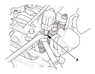
4.

If you feel too much or too little drag, loosen the locknut, and turn the adjusting screw (A) until the drag on the feeler gauge is correct.


5.

Tighten the locknut to the specified torque, and recheck the clearance. Repeat the adjustment if necessary.


Specified Torque

7 x 0.75 mm

14 N·m (1.4 kgf·m, 10 lbf·ft)

Apply new engine oil to the nut threads.


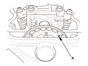
6.

Rotate the crankshaft clockwise. Align the No. 3 piston TDC groove (A) on the camshaft sprocket with the top edge of the head.


7.

Check and, if necessary, adjust the valve clearance on the No. 3 cylinder.


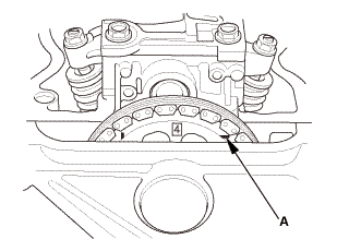
8.

Rotate the crankshaft clockwise. Align the No. 4 piston TDC groove (A) on the camshaft sprocket with the top edge of the head.


9.

Check and, if necessary, adjust the valve clearance on the No. 4 cylinder.


10.

Rotate the crankshaft clockwise. Align the No. 2 piston TDC groove (A) on the camshaft sprocket with the top edge of the head.


11.

Check and, if necessary, adjust the valve clearance on the No. 2 cylinder.


20. Cylinder Head Cover and/or Packing


1.

Thoroughly clean the head cover gasket and the groove.


NOTE: Check and, if necessary, replace the head cover gasket.


2.

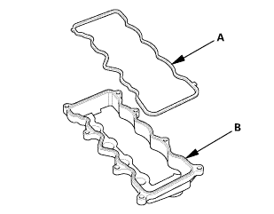
Install the head cover gasket (A) in the groove of the cylinder head cover (B).


3.

Make sure the head cover gasket is seated securely.


4.

Clean the head cover contacting surfaces with a shop towel.


5.

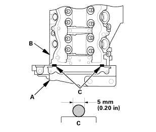
Remove the old liquid gasket from the top edge matting surfaces of the oil pump (A) and cylinder head (B).


6.

Apply liquid gasket (P/N 08718-0004 or 08718-0009) to the chain case contact areas. Install the component within 5 minutes of applying the liquid gasket.


NOTE:

Apply a 5 mm (0.20 in) diameter bead of liquid gasket to the mating surfaces (C).

If too much time has passed after applying the liquid gasket, remove the old liquid gasket and residue, then reapply new liquid gasket.


7.

Install the cylinder head cover.


8.

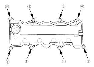
Tighten the bolts in two steps. In the final step, torque all bolts in sequence to 10 N·m (1.0 kgf·m, 7 lbf·ft).


NOTE:

Wait at least 30 minutes before filling the engine with oil.

Do not run the engine for at least 3 hours after installing the head cover.


9.

Connect the breather hose (A).


10.

Install the dipstick (B).


21. Auto Tensioner Assembly

inl.25mmssn-m

1.

Install the drive belt auto-tensioner.


22. Water Pump Pulley

1.

Install the water pump pulley.


23. Alternator

mmn-m(2

1.

Install the alternator.


i.nmm(n.i


2.

Connect the connector and the cable. Make sure the crimped side of the ring terminal faces away from the alternator when you connect it.


3.

Install the harness connector (A) and the harness clamps (B).


24. Drive Belt


1.

Move the auto-tensioner (A) counterclockwise.


2.

Install the drive belt (B).


25. Water Pump Pulley Mounting Bolt - Tighten

1.

Tighten the water pump pulley mounting bolts.


26. Thermostat Housing (Natural Gas Model)

imm

1.

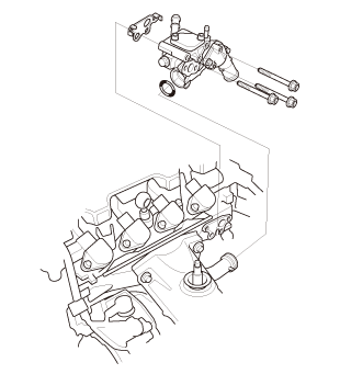
Install the thermostat housing (A), using a new gasket (B) and new O-ring (C).


27. Thermostat Housing Peripheral Assembly (Natural Gas Model)


1.

Connect the lower radiator hose (A), the water bypass hose (B), and the heater hose (C).


2.

Install the harness bracket (D).


3.

Install the harness clamp (A).


4.

Connect the connector (B).


5.

Install the harness clamps (A).


6.

Connect the connectors (B).


28. Catalytic Converter (Natural Gas Model)

:1mm.....


1.

Install the catalytic conveter cover (A).


2.

Install the catalytic converter (B) with new gaskets (C).


29. Exhaust Pipe A (Except CVT)

inmm125mm22i21

1.

Install exhaust pipe A. Use new gaskets (B) and new self-locking nuts (C).


30. Secondary HO2S


1.

Install secondary HO2S (A).


2.

Connect the connector.


31. Engine Undercover

1.

Install the engine undercover (A).


32. Splash Shield

1.

Install the splash shield (A).


33. Exhaust Chamber Cover (Natural Gas Model)

1.

Install the exhaust chamber cover (A).


34. A/F Sensor (Sensor 1)


1.

Install the A/F sensor (A).


2.

Connect the connector.


35. Ignition Coil

1.

Install the ignition coils.


36. Cylinder Head Peripheral Assembly

1.

Connect the upper radiator hose (A), the heater hose (B), and the water bypass hose (C).


2.

Install the harness holder (A) to the cylinder head.


3.

Install the harness clamps (A).


4.

Connect the PCV hose to the clamp (B).


5.

Install the harness holders (A).


6.

Connect the connectors (B).


37. Intake Manifold Assembly (Natural Gas Model)

mm


1.

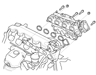
Install the intake manifold assembly (A) with new gaskets (B).


2.

Tighten the bolts/nuts in a crisscross pattern in three steps, beginning with the inner bolt.


3.

Install the connectors (A).


4.

Connect the harness clamps.


5.

Install the intake manifold bracket.


6.

Install the heater hose clamp bracket.


7.

Connect the EVAP canister hose (A), the brake booster vacuum hose (B), and the PCV hose (C).


38. Throttle Body - Install (Natural Gas Model)

mmm.uimm

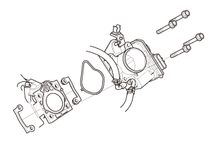
1.

Install the throttle body (A) with new gasket (B).


39. Intake Air Duct

1.

Install the intake air duct.


40. Fuel Feed Hose (Natural Gas Model)

1.

Connect the fuel feed hose (A) with a new O-ring (B).


41. Under Cowl Panel

22mm)2222

1.

Install the under cowl panel (A).


42. Center Cowl Cover


1.

If necessary, install the hood rear seal (A).


2.

Connect the windshield washer tube (B).


3.

Install the center cowl cover (C).


43. Both Side Cowl Covers


1.

Install the side cowl cover (A).


2.

The left side is shown; repeat on the right side.


44. Wiper Arm Assembly

1.122


NOTE: Set the wiper arms to the auto-stop position before installation.


1.

Install the wiper arms (A).


2.

Install the cowl top wiper covers (B).


45. Air Cleaner


1.

Install the harness clamp (A).


2.

Install the air cleaner (B).


3.

Connect the intake air duct (C).


46. Intake Air Pipe

1.

Install the intake air pipe.


47. Engine Cover

1.

Install the engine cover.


48. Battery

1.

Install the battery (A) and the battery setting plate (B).


NOTE: Do not deform the battery setting plate by over-tightening the nuts.


49. Battery Terminal - Reconnection


NOTE: If the battery performs abnormally, test the battery.


1.

Clean the battery terminals.


2.

Connect the positive cable (A) to the battery.


NOTE: Always connect the positive side first.


3.

Connect the negative cable and the battery sensor (B) to the battery.


NOTE: To protect the battery sensor connector (C) from damage, do not hold it when installing the negative terminal.


4.

Apply multipurpose grease to the terminals to prevent corrosion.


50. Manual Shut-off Valve - Open (Natural Gas Model)

1.

Open the manual shut-off valve (A).


51. Fuel Supply System Leak - Inspection (Natural Gas Model)

Check for a gas leak if there is an odor coming from the vehicle. Compressed natural gas (CNG) can only be smelled, not seen.


1.

Open the hood and the fuel fill door.


2.

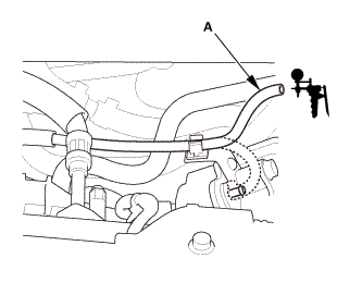
Connect a vacuum pump/gauge, 0-30 inHg, to the hose (A) from fuel pressure regulator P1, and apply 67.7 kPa (20.0 inHg, 508 mmHg) of vacuum.


3.

If fuel pressure regulator P2 does not hold vacuum, replace it before continuing to the next step.


4.

Inspect the fuel lines and hoses under the hood for kinks, abrasion, and other signs of damage.


5.

With the manual shut-off valve open, turn the ignition switch to ON (II), but do not start the engine.


6.

After the fuel pressure regulator shut-off solenoid valve/fuel tank internal solenoid valve operates for about 2 seconds, the fuel pressure in the fuel lines rises.


7.

Turn the ignition switch to LOCK (0).


8.

Repeat this two or three times.


9.

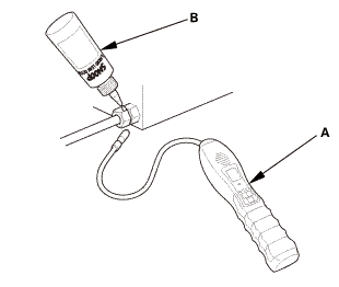
Within 1 minute, check for any damaged lines with a leak detector (A) (Snap-on Combustible Gas Leak Detector or Snoop Liquid Leak Detector (B)).


10.

If no damage was noticed during the inspection, turn the ignition switch to ON (II) for 2 seconds, then turn the ignition switch to LOCK (0).


11.

Within 1 minute, check for a leak at the vent hose outlet inside the fuel pipe protector (A).


12.

If you detect a leak, remove the vent hose, and check the fuel lines and fittings at the in-tank solenoid valve and the join block with a leak detector.


13.

If you cannot find the leak, raise the vehicle on a lift, remove the under-floor cover.


14.

Inspect all the fuel lines under the vehicle, visually, and with a leak detector.


15.

If you still cannot find the leak, remove the rear seat, then check all fuel lines and fittings at the fuel tank and the fuel joint block.


52. Radiator Coolant - Replacement (Natural Gas Model)

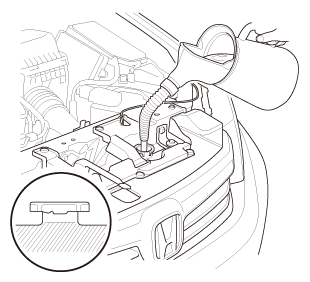
1.

Follow the chart and pour coolant into the radiator up to the base of the filler neck.


NOTE:

Use Honda Long Life Antifreeze/Coolant Type 2, and if necessary add Honda Extreme Cold Weather Antifreeze/Coolant Type 2 (concentrate). Using a non-Honda coolant can result in corrosion, causing the cooling system to malfunction or fail.

Honda Long Life Antifreeze/Coolant Type 2 is a mixture of 50 % antifreeze and 50 % water. Honda Extreme Cold Weather Antifreeze/Coolant Type 2 is a 100% concentration coolant. Do not add water to either coolant.

If the vehicle is regularly driven in very low temperatures (below -22 °F ( -30 °C)), a 60 % concentration of coolant should be used.


Operation

Vehicle Usage (Desired Mixture)

Current Mixture

Coolant Drain

Add Amount of Honda Extreme Cold Weather Antifreeze/Coolant Type 2 (100% concentrate)

Then add Honda Long Life Antifreeze/Coolant Type 2 (50/50)

Coolant Change

Normal Area (50/50)

50/50
60/40
unknown

Drain radiator, engine block, and reservoir

None

Top off the cooling system

Very Cold Area (60/40)

50/50
unknown

Drain radiator, engine block, and reservoir

About 1.3 L (44 fl oz)

60/40

About 1.1 L (37 fl oz)

Engine Overhaul

Normal Area (50/50)

-

-

None

Very Cold Area (60/40)

-

-

About 1.1 L (37 fl oz)

Coolant Winterizing

Very Cold Area (60/40)

50/50

Drain about 2.0 L (68 fl oz) from radiator

About 1.1 L (37 fl oz)

unknown*

Drain radiator, engine block, and reservoir


*: When you want to winterize the coolant with the minimum amount of coolant change but the current coolant concentration in the vehicle is unknown, you must drain all coolant from the cooling system.


Engine Coolant Capacities (Including the coolant reservoir capacity of 0.475 L (0.1255 US gal))


At Coolant Change

5.50 L (1.453 US gal)

After Engine Overhaul

6.51 L (1.720 US gal)


53. Tire and Wheel-Installation, Front Right

mminmuan

1.

Install the right front wheel.


NOTE: Before installing the wheel, clean the mating surfaces between the brake disc and the inside of the wheel.


54. Warm Up The Engine

Start the engine. Hold the engine speed at 3,000 rpm without load (A/T in P or N, M/T in neutral) until the radiator fan comes on, then let it idle.


55. HDS DLC - Connection


1.

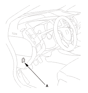
Connect the HDS to the data link connector (DLC) (A) located under the driver's side of the dashboard.


2.

Turn the ignition switch to ON (II).


3.

Make sure the HDS communicates with the vehicle. If it does not communicate, go to the DLC circuit troubleshooting.


56. Idle Speed - Inspection (Natural Gas Model)

NOTE:

Before checking the idle speed, check these items:


The malfunction indicator lamp (MIL) has not been reported on, and there are no DTCs.

Ignition timing

Spark plugs

Air cleaner

PCV system


Apply the parking brake, and make sure the headlights are off.


1.

Check the idle speed without load conditions: headlights, blower fan, radiator fan, and air conditioner off.


Idle speed should be: 670±50 rpm (in P or N)


2.

Let the engine idle for 1 minute with high electric load (A/C on, temperature set to max cool, blower fan on high, headlights on high beam).


Idle speed should be: 710±50 rpm (in P or N)


NOTE: If the idle speed is not within specification, do the PCM idle learn procedure. If the idle speed is still not within specification, go to the symptom troubleshooting.


57. CKP Pattern Clear/CKP Pattern Learn

1.

Select CRANK PATTERN in the ADJUSTMENT MENU with the HDS.


2.

Select CRANK PATTERN CLEAR, and clear the CKP pattern.


3.

Select CRANK PATTERN LEARNING with the HDS, and follow the screen prompts.


58. Ignition Timing - Inspection


1.

Jump the SCS line with the HDS.


2.

Connect the timing light to the No. 1 ignition coil harness.


3.

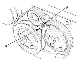
Aim the light toward the pointer (A) on the cam chain case. Check the ignition timing under a no load condition (headlights, blower fan, rear window defogger, and air conditioner are turned off).


Ignition Timing

8±2 ° BTDC (RED mark (B)) at idle


4.

If the ignition timing differs from the specification, check the camshaft timing. If the camshaft timing is OK, update the ECM/PCM if it does not have the latest software, or substitute a known-good ECM/PCM, then recheck. If the system works properly, and the ECM/PCM was substituted, replace the original ECM/PCM.


5.

Disconnect the HDS and the timing light.


59. Maintenance Minder Reset

1.

After doing all procedures, select the individual maintenance item you wish to reset with the HDS..


Valvetrain
...

Valve Guide Replacement (R18Z1)
1. Vehicle Lift 1. Raise the vehicle on a lift, and make sure it is securely supported. 2. ...

See also:

Honda Civic Owners Manual. HFL Buttons
(Pick-up) button: Press to go directly to the Phone screen or to answer an incoming call. (Hang-up/back) button: Press to end a call or to cancel a command. (Talk) button: Press to call a number with a stored voice tag. (Phone) button: Press to go directly to the Phone screen. ...

© 2016-2024 Copyright www.hocivic.com

0.0129