Honda Civic Service Manual: Steering Angle Sensor Removal and Installation
5101A0

Removal
|
SRS components are located in this area. Review the SRS component locations, and the precautions and procedures before doing repairs or service. |
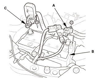
| 1. | Battery Terminal (SRS) - Disconnection |
|
|
|
|||||||||||||||
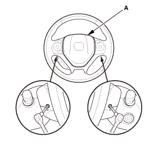
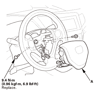
| 2. | Driver's Airbag |
|
|
|
|
|
|
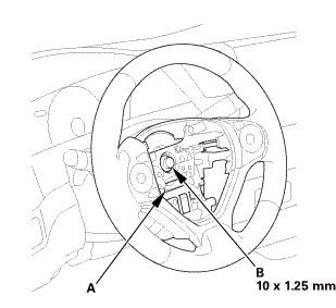
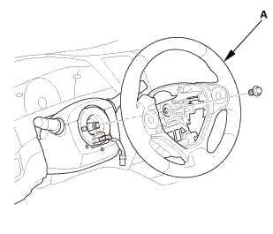
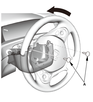
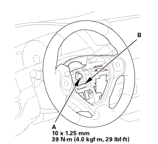
| 3. | Steering Wheel Assembly |
|
|
|
 wxusmm
|
|
|
||||||||||||||||||||

|
|
|
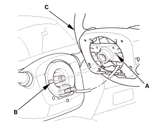
| 4. | Upper Column Cover |
|
|
|
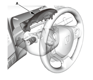
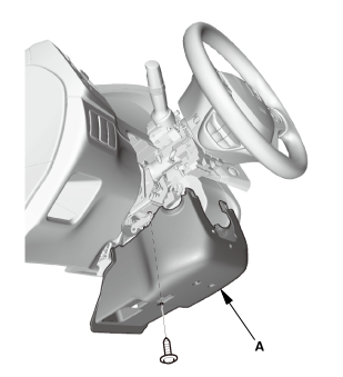
| 5. | Lower Column Cover |
|
|
|
|
|
|
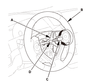
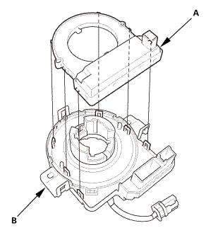
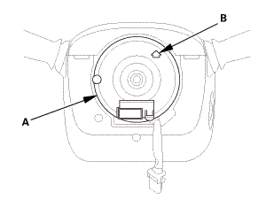
| 6. | Cable Reel/Steering Angle Sensor |
|
|
|

|
|
|

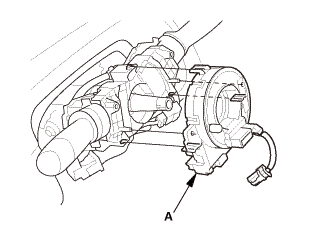
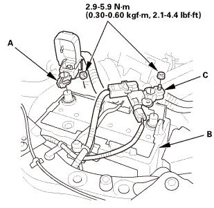
| 7. | Steering Angle Sensor |
|
|
|

Installation
|
SRS components are located in this area. Review the SRS component locations, and the precautions and procedures before doing repairs or service. |
| 1. | Steering Angle Sensor |
|
|
|

| 2. | Cable Reel/Steering Angle Sensor |
|
|
|
|
|
|
| 3. | Lower Column Cover |
|
|
|
|
|
|
| 4. | Upper Column Cover |
|
|
|

| 5. | Steering Wheel Assembly |
|
|
|
|
|
|
|||||||||
|
|
|
 no
no| 6. | Driver's Airbag |
|
|
|
||||||||||
 mmmmin)in!
|
|
|
||||||||||||

| 7. | Battery Terminal (SRS) - Reconnection |
|
|
|
||||||||||||||||
 (o.2ao.sam.
| 8. | Confirm Proper SRS Operation |
|
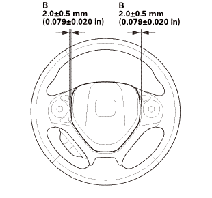
| 9. | Steering Wheel Spoke Angle - Check |
|
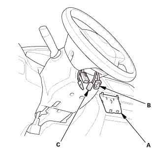
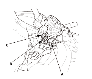
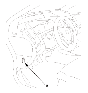
| 10. | HDS DLC - Connection |
|
|
|
| 11. | VSA Sensor Neutral Position - Memorization |
|
||||||||||
| 12. | Steering Angle Sensor Neutral Position - Clear |
|
|||||||
 Steering Angle Sensor Neutral Position Clear
Procedure
1.
HDS DLC - Connection
1.
Connect the HDS to the data link connector (DLC) (A) located
under the ...
 Wheels/Tires
...
See also:
Honda Civic Owners Manual. Specifications
2.0 L engine models
Vehicle Specifications
Air Conditioning
Engine Specifications
Fuel
Washer Fluid
Light Bulbs
Brake/Clutch* Fluid
Continuously Variable Transmission Fluid
Manual Transmission Fluid
Engine Oil
Engine Coolant
Tire
1.5 L engine ...
