|
|
Use commercially available computerized four wheel alignment
equipment to measure wheel alignment (caster, camber, toe, and turning
angle). Follow the equipment manufacturer's instructions.
|
|
1.
|
Check the camber angle.
|
|
USA and Canada models
|
Camber angle:
|
| |
Except Si:
|
| |
|
Front:
|
0 ° 00 ’±30 ’
|
| |
|
Rear:
|
-0 ° 45 ’±45 ’
|
| |
Si (Without 18 inch wheel):
|
| |
|
Front:
|
-0 ° 04 ’±30 ’
|
| |
|
Rear:
|
-0 ° 52 ’±45 ’
|
| |
Si (With 18 inch wheel):
|
| |
|
Front:
|
-0 ° 18 ’±30 ’
|
| |
|
Rear:
|
-0 ° 45 ’±45 ’
|
|
(Maximum difference between the front right and
left side: 0 ° 45 ’)
|
|
|
|
|
Mexico models
|
Camber angle:
|
| |
Front:
|
0 ° 20 ’±30 ’
|
| |
Rear:
|
-0 ° 22 ’±45 ’
|
|
(Maximum difference between the front right and
left side: 0 ° 45 ’)
|
|
|
|
|

|
If the measurement is within specification, measure
the toe-in.
|
|
|
|
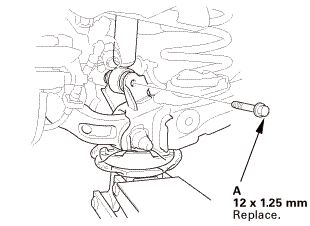
If the measurement for the front camber is not
within the specification, go to front camber adjustment.
|
|
|
|
If the measurement for the rear camber is not
within the specification, check for bent or damaged
suspension components.
|
|
|
|

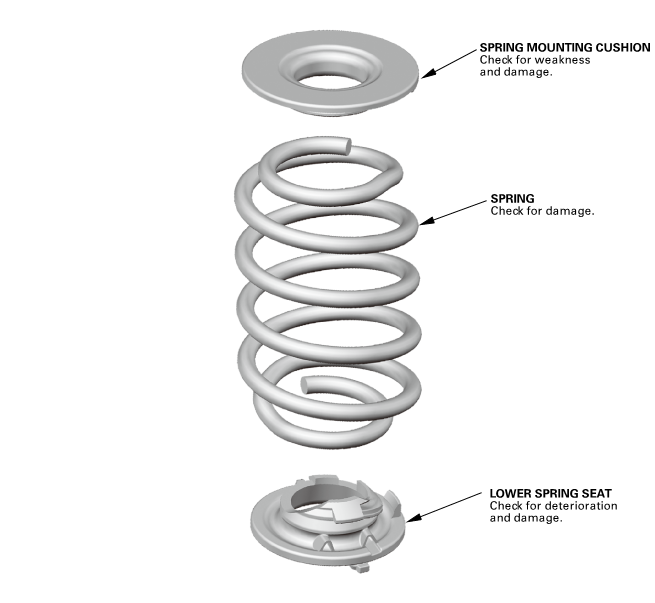 cusmoucheckorandlowersunand
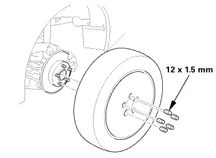
 i2xi2inln

 mmh5ummn)replace.
 125mmumngvum
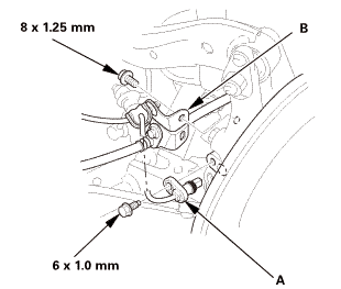
 125mmm,29
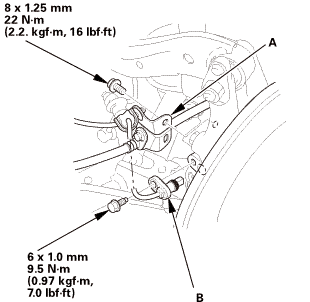 mmzzumm.s
 15mmumum
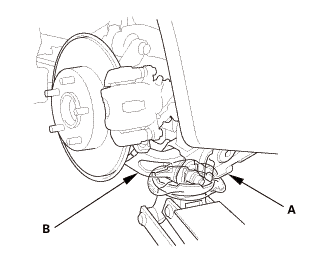
 Brake Calipers