Honda Civic Service Manual: M/T Differential Thrust Clearance Adjustment (K24Z7)
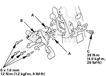
 Disassembly
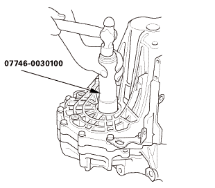
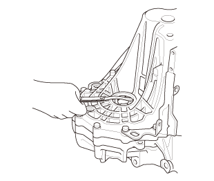
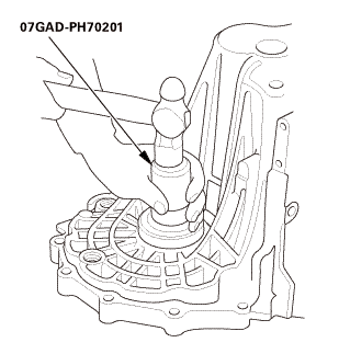
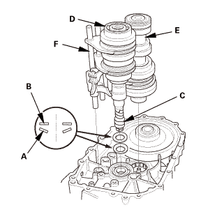
| 1. | M/T Change Lever Assembly |
|
|
|
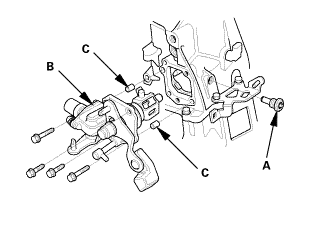
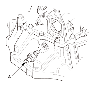
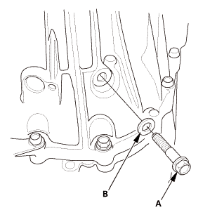
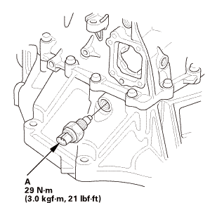
| 2. | Back-Up Light Switch |
|
|
|
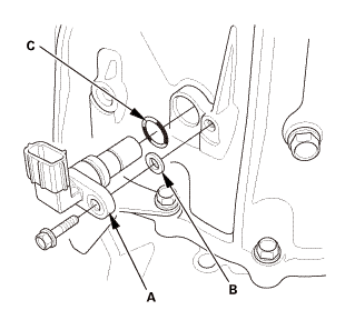
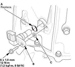
| 3. | Output Shaft (Countershaft) Speed Sensor |
|
|
|
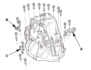
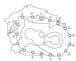
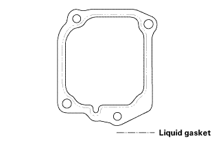
| 4. | Transmission Housing |
|
|
|
|
|
|
|
|
|
|
|
|
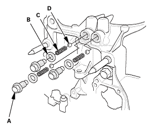
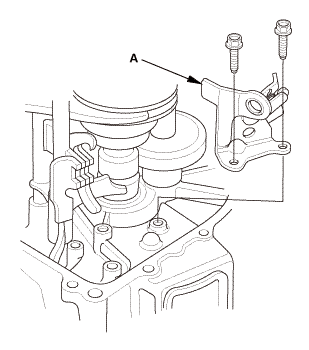
| 5. | Reverse Shift Fork |
|
|
|
| 6. | Baffle Plate |
|
|
|
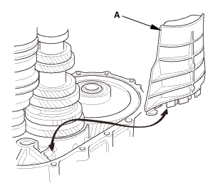
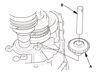
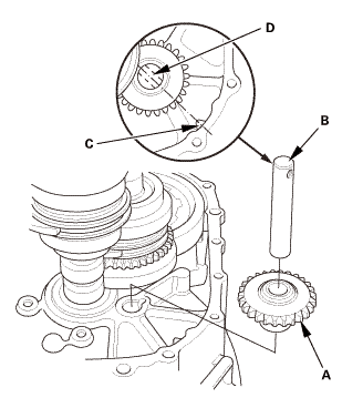
| 7. | Reverse Idler Gear |
|
|
|
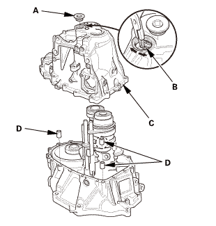
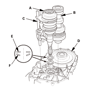
| 8. | M/T Mainshaft and Countershaft and Shift Fork Assembly |
|
|
|
|||||||||||||||
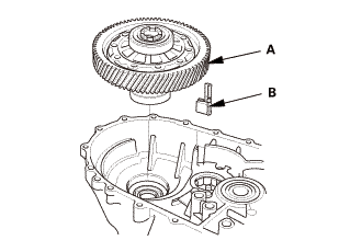
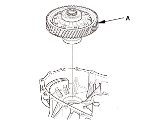
| 9. | Differential Assembly |
|
|
|
 Adjustment
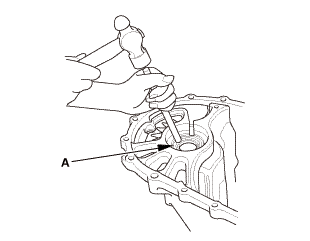
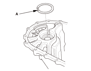
| 1. | M/T Differential Thrust Clearance Adjustment |
|
|
|
||||||
|
|
|
|
|
|
|
|
|
|||||||||||||
|
|
|
|
|
|
||||||||||||||||||||||||||||||||||||||||||||||||||||||||||||
|
|
|
 Reassembly
| 1. | Differential Assembly |
|
|
|
|||||||||

| 2. | M/T Mainshaft and Countershaft and Shift Fork Assembly |
|
|
|
||||||||||||||||||
| 3. | Reverse Idler Gear |
|
|
|
| 4. | Baffle Plate |
|
|
|
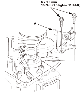
| 5. | Reverse Shift Fork |
|
|
|
 mmlbf!
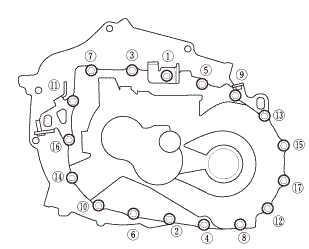
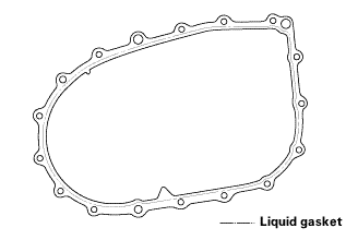
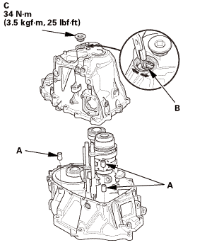
| 6. | Transmission Housing |
|
|
|
||||||||||||||||||||

|
|
|
|||||||||||||||
|
|
|
|||||||||||||||||||||||
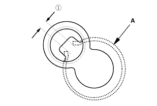
 as installed:
3.3-6.0 mm (0.130-0.236 in)
as installed:
3.3-6.0 mm (0.130-0.236 in)|
|
|
|
|
|
||||||||||
|
|
|
|
|
|
| 7. | Output Shaft (Countershaft) Speed Sensor |
|
|
|
| 8. | Back-Up Light Switch |
|
|
|
| 9. | M/T Change Lever Assembly |
|
|
|
||||||||||||||||||||
 iukn
iukn|
|
|
 Left M/T Differential Oil Seal Replacement (R18Z1 M/T)
2191F4 LEFT
1.
Vehicle Lift
1.
Raise the vehicle on a lift, and make sure it is securely supported.
...
 Right A/T Differential Oil Seal Replacement (A/T)
2191M0 RIGHT
1.
Vehicle Lift
1.
Raise the vehicle on a lift, and make sure it is securely supported.
...
See also:
Honda Civic Owners Manual. Opening the Hood
Park the vehicle on a level surface, and set
the parking brake.
Pull the hood release handle under the
driver's side lower left corner of the
dashboard.
► The hood will pop up slightly.
Pull up the hood latch lever (located under
the front edge of the hood to ...
