Honda Civic Service Manual: M/T Countershaft Assembly Clearance Inspection (K24Z7)

Removal
| 1. | M/T Change Lever Assembly |
|
|
|
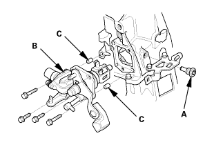
| 2. | Back-Up Light Switch |
|
|
|
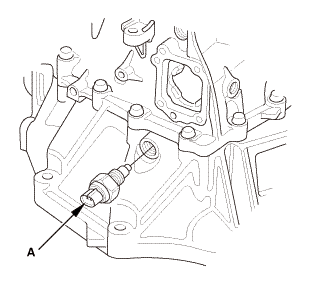
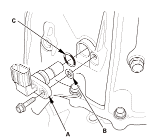
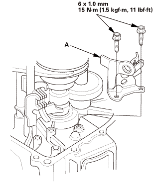
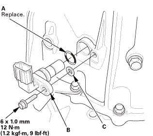
| 3. | Output Shaft (Countershaft) Speed Sensor |
|
|
|
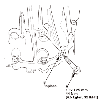
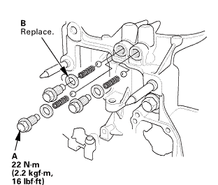
| 4. | Transmission Housing |
|
|
|
|
|
|
|
|
|
|
|
|
| 5. | Reverse Shift Fork |
|
|
|
| 6. | Baffle Plate |
|
|
|
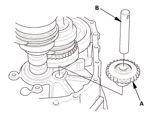
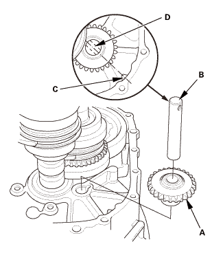
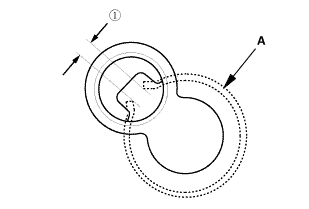
| 7. | Reverse Idler Gear |
|
|
|
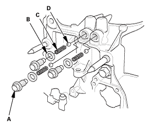
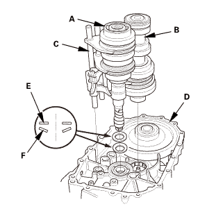
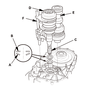
| 8. | M/T Mainshaft and Countershaft and Shift Fork Assembly |
|
|
|
|||||||||||||||
 Inspection
|
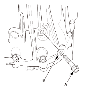
NOTE: Before inspection, make sure the special bolt is tightened to the specified torque. |
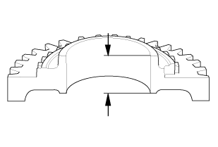
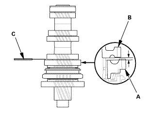
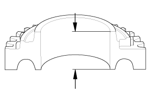
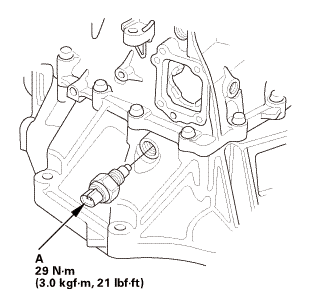
| 1. | Countershaft Assembly Clearance Inspection |
|
|
|
|||||||||||||||||||||||

|
|
|
|||||||||||||||||||||
|
|
|
|||||||||||||||||||||||
|
|
|
||||||||||||
|
|
|
|||||||||||||||||||||
|
|
|
|||||||||||||||||||||||

Installation
| 1. | M/T Mainshaft and Countershaft and Shift Fork Assembly |
|
|
|
||||||||||||||||||
| 2. | Reverse Idler Gear |
|
|
|
| 3. | Baffle Plate |
|
|
|
| 4. | Reverse Shift Fork |
|
|
|
 mmlbf!
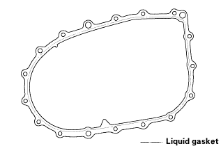
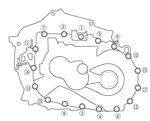
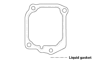
| 5. | Transmission Housing |
|
|
|
||||||||||||||||||||
|
|
|
|||||||||||||||
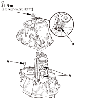
|
|
|
|||||||||||||||||||||||
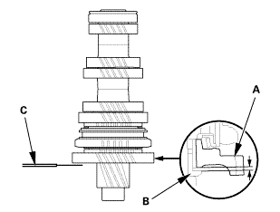
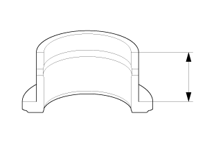
 as installed:
3.3-6.0 mm (0.130-0.236 in)
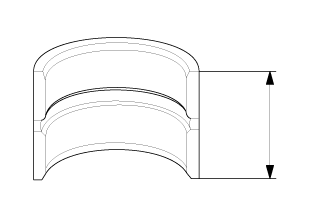
as installed:
3.3-6.0 mm (0.130-0.236 in)|
|
|
|
|
|
||||||||||
|
|
|
|
|
|
| 6. | Output Shaft (Countershaft) Speed Sensor |
|
|
|
| 7. | Back-Up Light Switch |
|
|
|
| 8. | M/T Change Lever Assembly |
|
|
|
||||||||||||||||||||
 iukn
iukn|
|
|

 M/T Countershaft Assembly Clearance Inspection (R18Z1 M/T)
Removal
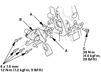
1.
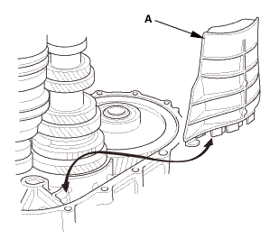
M/T Change Lever Assembly
1.
Remove the change lever assembly (A).
...
See also:
Honda Civic Owners Manual. Playing Bluetooth’ Audio
Your audio system allows you to listen to music from your
Bluetooth-compatible
phone.
This function is available when the phone is paired and connected to the
vehicle’s
Bluetooth’ HandsFreeLink’ (HFL) system.
Phone Setup
Playing Bluetooth’ Audio
Not all Bluetooth-enabled phones ...
