Honda Civic Service Manual: Camshaft Inspection (R18Z1)

| 1. | Vehicle Lift |
|
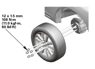
| 2. | Tire and Wheel-Removal, Front Right |
|
|
|
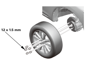 12x1mm
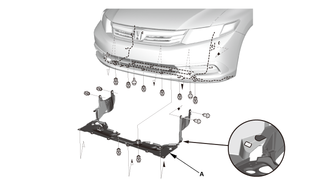
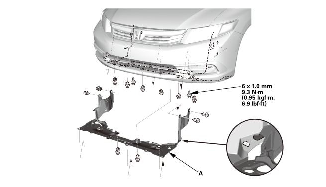
| 3. | Splash Shield |
|
1. |
Remove the splash shield (A). |
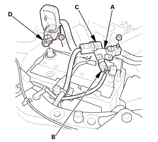
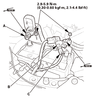
| 4. | Battery Terminal - Disconnection |
|
|
|
|||||||||||||||||||||||||||

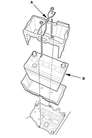
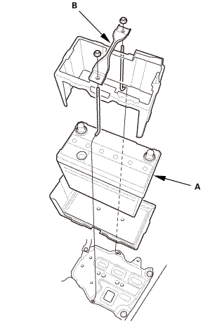
| 5. | Battery |
|
|
|
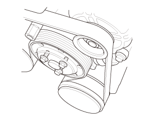
| 6. | Water Pump Pulley Mounting Bolt - Loosen |
|
|
|
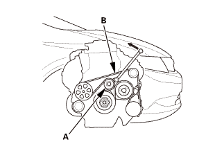
| 7. | Drive Belt |
|
|
|
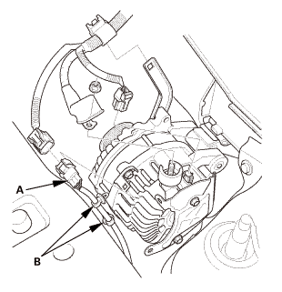
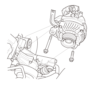
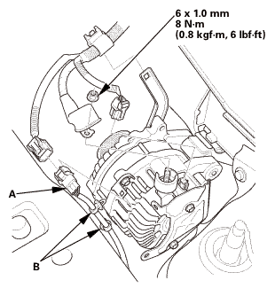
| 8. | Alternator |
|
|
|
|
|
|
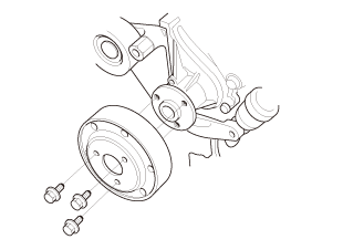
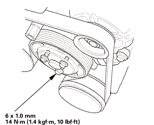
| 9. | Water Pump Pulley |
|
|
|
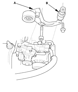
| 10. | Auto Tensioner Assembly |
|
|
|
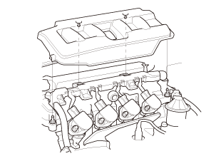
| 11. | Engine Cover |
|
|
|
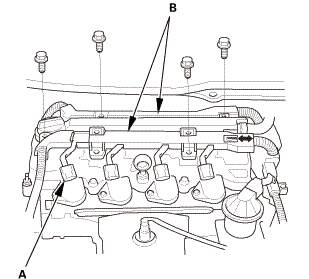
| 12. | Cylinder Head Cover Peripheral Assembly |
|
|
|
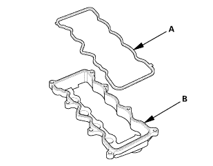
| 13. | Cylinder Head Cover and/or Packing |
|
|
|
|
|
|
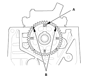
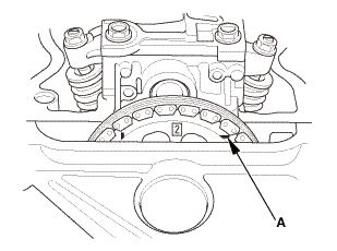
| 14. | Check The No.1 Piston at Top Dead Center (With Cam Chain Case/Oil Pump) |
|
|
|
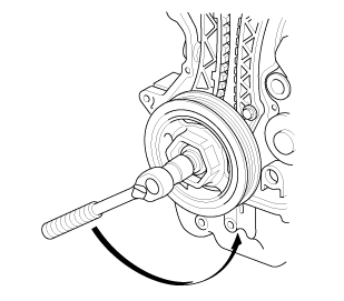
| 15. | Crankshaft Pulley |
|
|
|
 [av
[av| 16. | Engine Jack Support (State Of A Low Vehicle) |
|
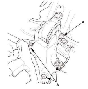
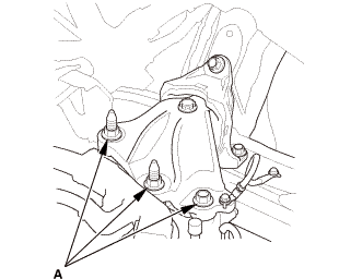
| 17. | Mounting Bracket, Engine Side |
|
|
|
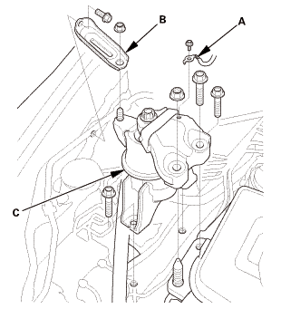
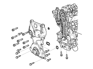
| 18. | Engine Oil Pump Assembly |
|
|
|
|
|
|
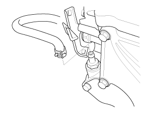
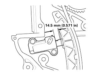
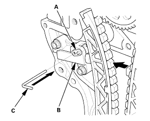
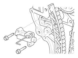
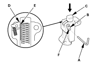
| 19. | Cam Chain Auto-Tensioner |
|
|
|
||||||||||||
|
|
|
|
|
|
||||||||||||
|
|
|
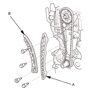
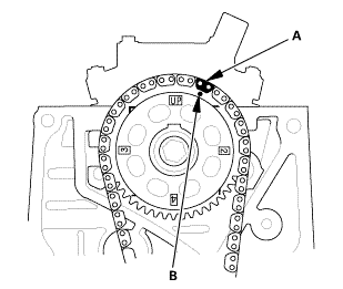
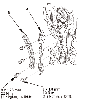
| 20. | Cam Chain |
|
|
|
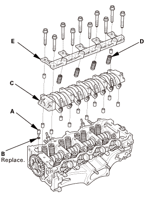
| 21. | Rocker Arm Assembly |
|
|
|
|
|
|
|
|
|
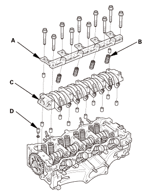
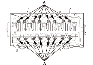
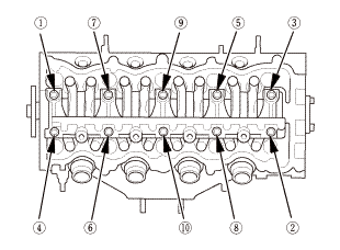
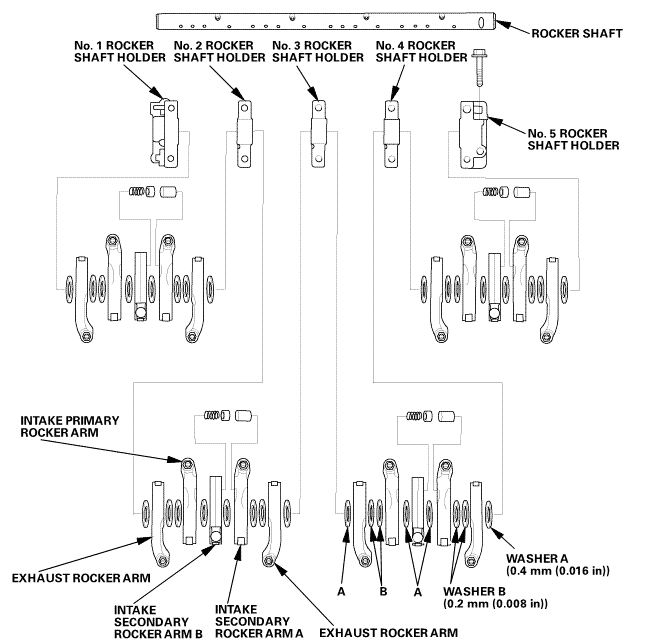
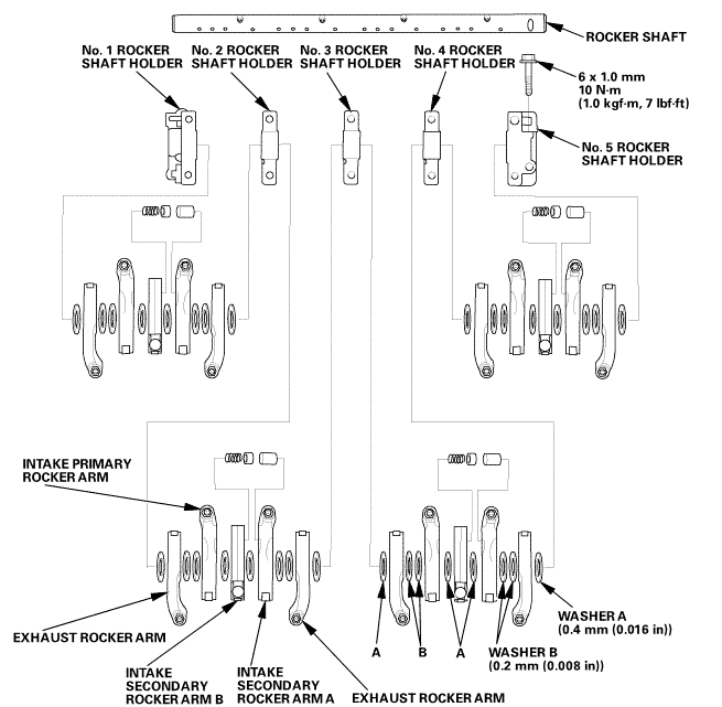
| 22. | Rocker Arm Assembly - Disassembly |
|
NOTE: |
|
|||
|
|||
|
|||
|
|||
|
 shafyna.na.holderj.inmm
| 23. | Camshaft Sprocket |
|
|
|

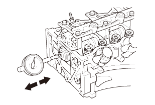
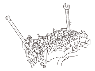
| 1. | Camshaft End Play - Inspection |
|
|
|
|||||||||||||
|
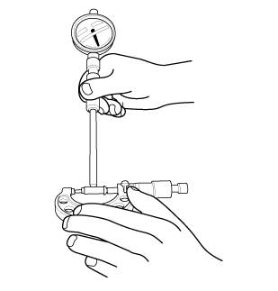
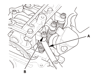
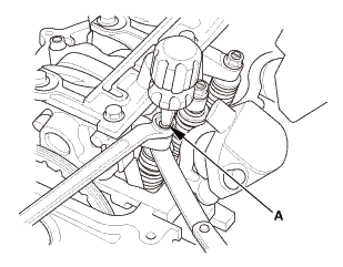
3. |
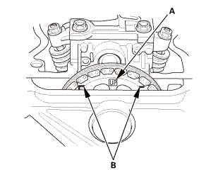
Zero the dial indicator against the end of the camshaft, then push the camshaft back and forth, and read the end play. If the end play is beyond the service limit, replace the thrust cover and recheck. If it is still beyond the service limit, replace the cylinder head. If it is still beyond the service limit, replace the camshaft. |
|||||||||
|
NOTE: Do not rotate the camshaft during inspection. |
||||||||||
|
||||||||||
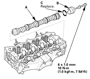
| 1. | Camshaft |
|
|
|
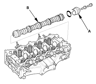
| 1. | Camshaft - Inspection |
|
|
|
|
|
|
|
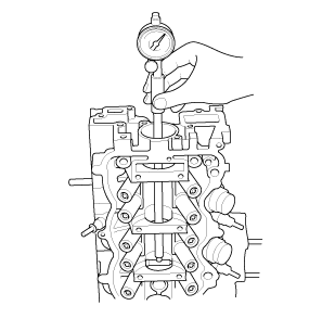
4. |
Clean the camshaft bearing surfaces in the cylinder head. Measure the inside diameter of each camshaft bearing surface, and check for an out-of-round condition: |
|||||||||||||
|
||||||||||||||
|
||||||||||||||
|
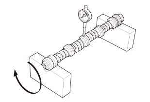
5. |
Check the total runout with the camshaft supported on V-blocks. |
|||||||||
|
||||||||||
|
||||||||||
|
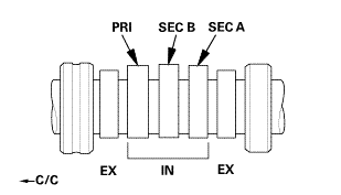
6. |
Measure the cam lobe height. |
|||||||||||||
|
Cam Lobe Height Standard (New): |
||||||||||||||
|
USA and Canada models
|
||||||||||||||
|
Mexico models
|
||||||||||||||
|
||||||||||||||
 secasx
|
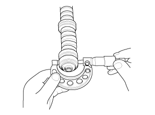
7. |
Remove the rocker shaft holders and the lost motion holder |

| 1. | Camshaft |
|
|
|
 tommnomm
| 2. | Camshaft Sprocket |
|
|
|
||||||||||||||||||||||
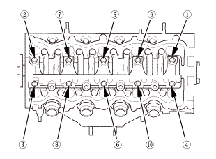
| 3. | Rocker Arm Assembly - Reassembly |
|
NOTE: |
|
|||
|
|||
|
|||
|
|||
|
 shafy[hiinyakeprimarvnockinarminmm
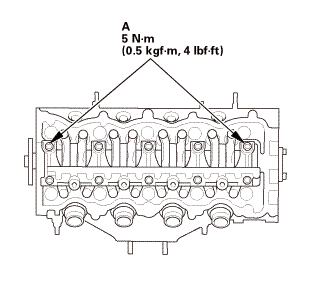
| 4. | Rocker Arm Assembly |
|
|
|
|||||||||||||||
|
|
|
|
|
|
||||||||||
| 5. | Set The Crankshaft To Top Dead Center |
|
|
|
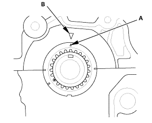
| 6. | Set The No.1 Piston at Top Dead Center (Without Cam Chain Case/Oil Pump) |
|
|
|
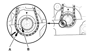
| 7. | Cam Chain |
|
|
|
|
|
|
|
|
|
 ...,is(1.2
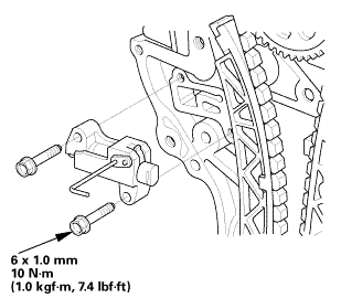
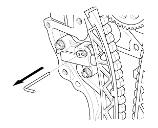
| 8. | Cam Chain Auto-Tensioner |
|
|
|
||||||
|
|
|
 nokvf-in.
|
|
|
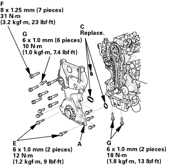
| 9. | Engine Oil Pump Assembly |
|
|
|
||||||||||||||||||||||||||
|
|
|
||||||||||||||
|
|
|
||||||||||||||||||||||||||||||
 25mm(7(32k1n1omm12
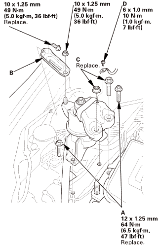
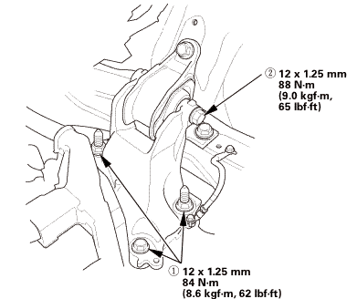
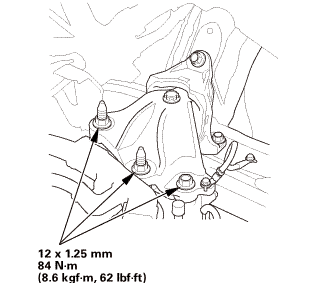
| 10. | Mounting Bracket, Engine Side |
|
|
|
 125mmnminm.:125mm
| 11. | Engine Jack Support (State Of A Low Vehicle) |
|
| 12. | Transmission Mount Bracket Mounting Bolt - Loosen |
|
M/T
A/T
|
|
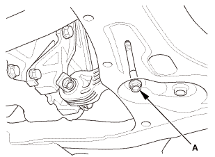
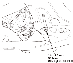
| 13. | Lower Torque Rod - Loosen |
|
|
|
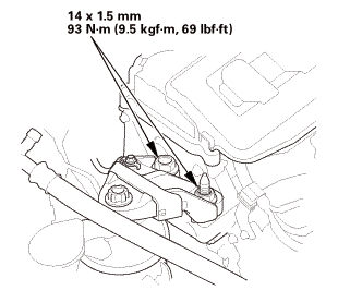
| 14. | Side Engine Mount - Tighten |
|
|
|
 nxl.mm
| 15. | Transmission Mount Bracket Mounting Bolt - Tighten |
|
1. |
Tighten the transmission mount bracket mounting bolt and nuts. |
M/T
 i2mm
i2mm
A/T
 nz
nz
| 16. | Lower Torque Rod Mounting Bolt - Tighten |
|
|
|
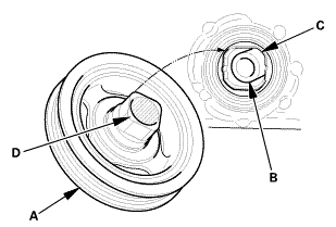
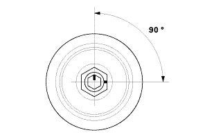
| 17. | Crankshaft Pulley |
|
|
|
|
|
|
|
|
|
|||||||||||||
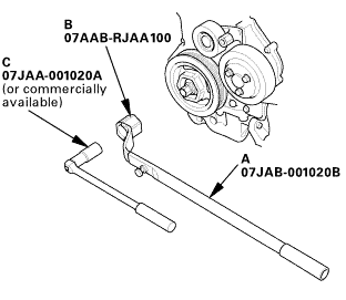
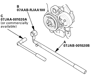 o7jaanmo2oa
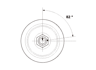
|
|
|
||||||||||
| 18. | Valve Clearance Adjustment |
|
|
|

|
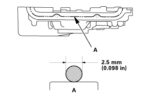
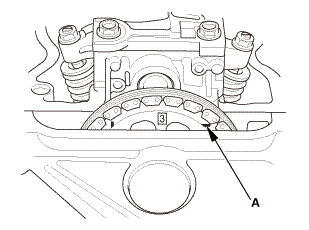
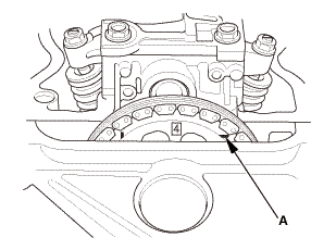
2. |
Select the correct feeler gauge for the valve clearance you are going to check. |
|||||||||
|
||||||||||
 no!
no!
|
|
|
|
|
|
|||||||||||||||
|
|
|
|
|
|
|
|
|
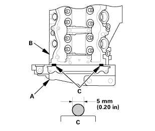
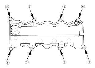
| 19. | Cylinder Head Cover and/or Packing |
|
|
|
|||||||||||||||
|
|
|
||||||||||||||||||||
|
|
|
||||||||||||||||||||
|
|
|
| 20. | Cylinder Head Cover Peripheral Assembly |
|
|
|
 mmidnmm,
| 21. | Engine Cover |
|
|
|
| 22. | Auto Tensioner Assembly |
|
|
|
 inl.25mmssn-m
| 23. | Water Pump Pulley |
|
|
|
| 24. | Alternator |
|
|
|
 mmn-m(2
|
|
|
 i.nmm(n.i
| 25. | Drive Belt |
|
|
|
| 26. | Water Pump Pulley Mounting Bolt - Tighten |
|
|
|
| 27. | Splash Shield |
|
1. |
Install the splash shield (A). |
| 28. | Tire and Wheel-Installation, Front Right |
|
|
|
||||||
 mminmuan
| 29. | Battery |
|
|
|
||||||
| 30. | Battery Terminal - Reconnection |
|
|
|
|||||||||||||||||||
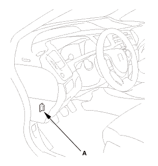
| 31. | HDS DLC - Connection |
|
|
|
| 32. | CKP Pattern Clear/CKP Pattern Learn |
|
 Valve Guide Replacement (R18Z1)
1.
Vehicle Lift
1.
Raise the vehicle on a lift, and make sure it is securely supported.
2. ...
 Camshaft Removal and Installation (K24Z7)
1.
Air Cleaner Assembly
1.
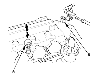
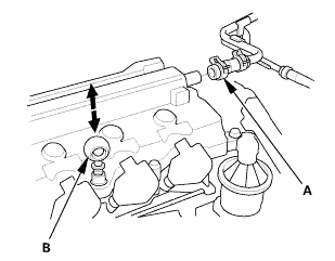
Disconnect the intake air duct (A) and the intake air pipe (B).
...
See also:
Honda Civic Owners Manual. Supplemental Restraint System (SRS) Indicator
When the ignition switch is turned to
ON *1
The indicator comes on for a few seconds,
then goes off. This tells you the system is
working properly.
If the indicator comes on at any other time, or does not come on at all, have
the
system checked by a dealer as soon as possible. If you don ...
