Honda Civic Service Manual: ATF Feed Pipe Removal and Installation (A/T)

Removal
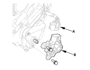
| 1. | Transmission Range Switch Cover |
|
|
|
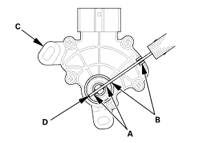
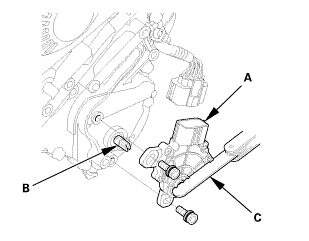
| 2. | Transmission Range Switch |
|
|
|
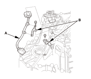
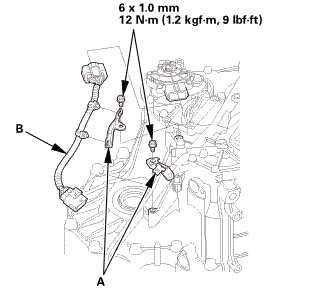
| 3. | Transmission Range Switch Subharness |
|
|
|
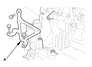
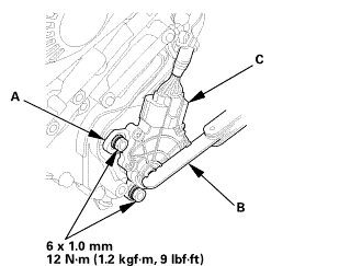
| 4. | ATF Warmer Bracket |
|
|
|
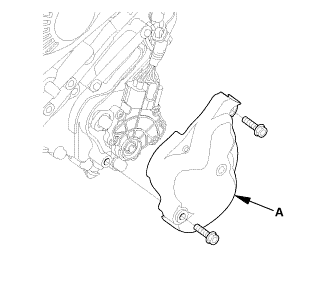
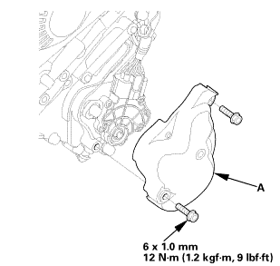
| 5. | Transmission End Cover |
|
|
|
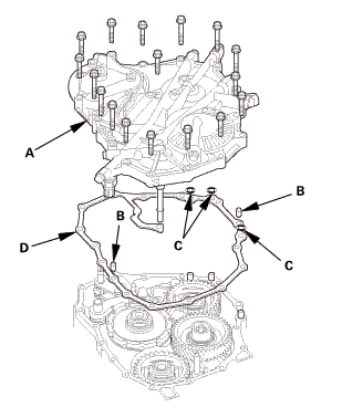
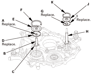
| 6. | ATF Feed Pipe |
|
|
|

Installation
|
NOTE: Apply a light coat of clean ATF on all moving parts before installation. |
| 1. | ATF Feed Pipe |
|
|
|
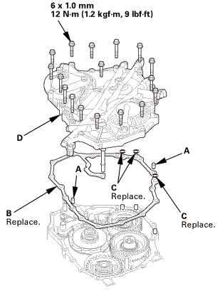
| 2. | Transmission End Cover |
|
|
|
 mm12u....um,!mk)
| 3. | ATF Warmer Bracket |
|
|
|
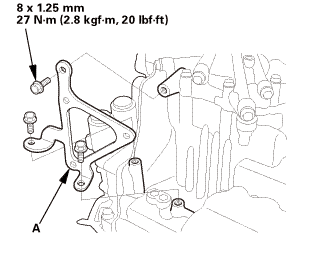 mm27lhf!
| 4. | Transmission Range Switch Subharness |
|
|
|
| 5. | Transmission Range Switch |
|
|
|
||||||

|
|
|
||||||
|
|
|
|
|
|
||||||||||||
| 6. | Transmission Range Switch Cover |
|
|
|
 mmnm
mmnm Transmission Fluid Pressure Switch A (2nd Clutch) Removal and Installation (A/T)
2221A4 REAR
1.
Vehicle Lift
1.
Raise the vehicle on a lift, and make sure it is securely supported.
...
 A/T Shift Cable Removal and Installation (A/T)
214101
1.
Center Console Panel Assembly (Except '12M M/T)
1.
Detach the clips (A).
...
See also:
Honda Civic Service Manual. Moonroof Motor Removal and Installation (4-door)
729140
Removal
1.
Battery Terminal (SRS) - Disconnection
1.
Make sure the ignition switch is in LOCK (0).
...
