Honda Civic manuals

Honda Civic Service Manual: A/T Mainshaft Disassembly, Reassembly, and Inspection (A/T)

Honda Civic Service Manual / Powertrain / Transmission/Transaxle / Automatic / A/T Mainshaft Disassembly, Reassembly, and Inspection (A/T)

View

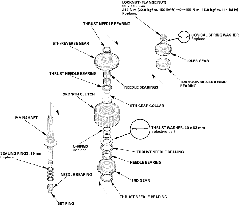
1. A/T Mainshaft Exploded View

Exploded View


mun......usuzzmzev.sunmmsmlssloummsmasmgearmmmmamthrust


Disassembly

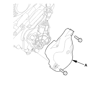
1. Transmission Range Switch Cover

1.

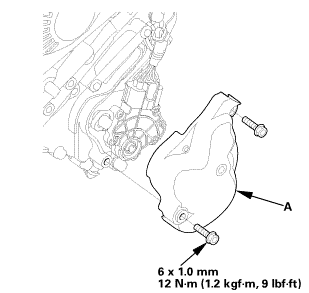
Remove the transmission range switch cover (A).


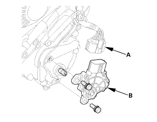
2. Transmission Range Switch


1.

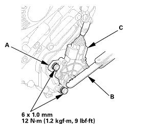
Disconnect the connector (A).


2.

Remove the transmission range switch (B).


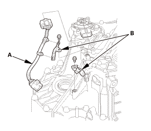
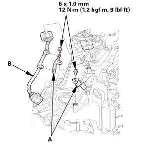
3. Transmission Range Switch Subharness


1.

Remove the transmission range switch subharness (A).


2.

Remove the clamp brackets (B).


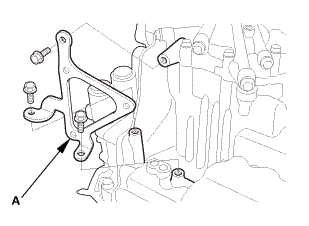
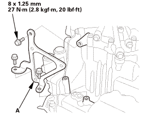
4. ATF Warmer Bracket

1.

Remove the ATF warmer bracket (A).


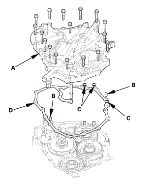
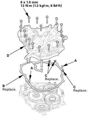
5. Transmission End Cover

1.

Remove the end cover (A), the dowel pins (B), the O-rings (C), and the end cover gasket (D).


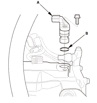
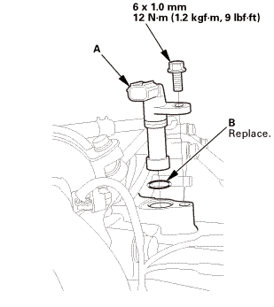
6. Input Shaft (Mainshaft) Speed Sensor

1.

Remove the input shaft (mainshaft) speed sensor (A) with the O-ring (B).


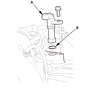
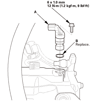
7. Output Shaft (Countershaft) Speed Sensor

1.

Remove the output shaft (countershaft) speed sensor (A) with the O-ring (B).


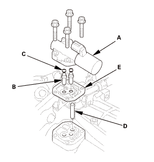
8. A/T Clutch Pressure Control Solenoid Valve A

1.

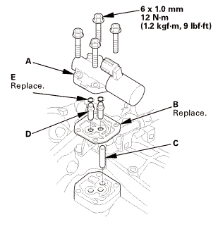
Remove A/T clutch pressure control solenoid valve A with the ATF joint pipes (B), the O-rings (C), the 35 mm ATF pipe (D), and the gasket (E).


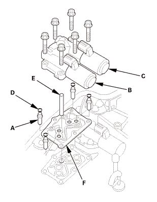
9. A/T Clutch Pressure Control Solenoid Valve B and C

1.

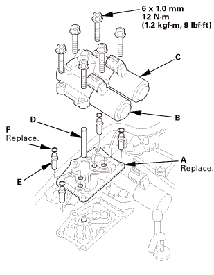
Remove A/T clutch pressure control solenoid valves B and C with the ATF joint pipes (A), the O-rings (D), the 50 mm ATF pipe (E), and the gasket (F).


10. ATF Filter Assembly


1.

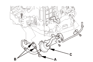
Remove the banjo bolt (A) with the sealing washers (B).


2.

Remove the ATF inlet line/ATF hose/ATF filter assembly (C).


11. A/T Solenoid Cover

1.

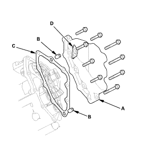
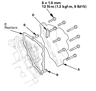
Remove the shift solenoid valve cover (A) with the dowel pins (B), the gasket (C), and the clamp bracket (D).


12. A/T Shift Solenoid Wire Harness - Disconnection

1.

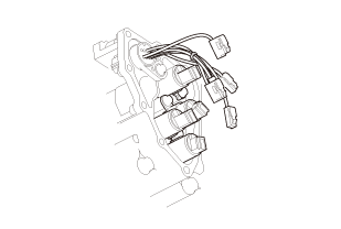
Disconnect the connectors.


13. ATF Pipe


1.

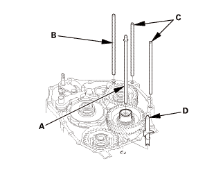
Remove the 6 x 199 mm ATF pipe (A).


2.

Remove the 8 x 192.5 mm ATF pipe (B).


3.

Remove the 8 x 180.5 mm ATF pipes (C).


4.

Remove the ATF lubrication pipe (D).


14. End Cover Idler Gear Assembly


1.

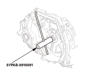
Install the mainshaft holder onto the mainshaft.


2.

Engage the park pawl with the park gear.


3.

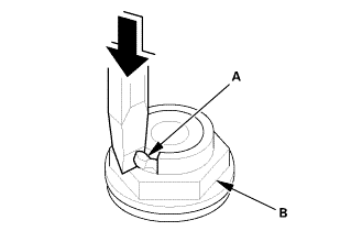
Using a chisel, cut the lock tab (A) of the locknut (B).


NOTE: Keep all of the chiseled particles out of the transmission.


4.

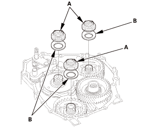
Remove the locknuts (A) and the conical spring washers (B) from each shaft.


NOTE:

The countershaft and secondary shaft locknuts have left-hand threads.

Keep all of the chiseled particles out of the transmission.

Clean the old locknuts; they are used to install the press fit idler gears and park gear.


5.

Remove the mainshaft holder.


6.

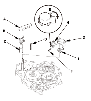
Remove the park pawl (A), the park pawl spring (B), the park pawl shaft (C), and the stop shaft (D).


7.

Pry down the lock tab of the lock washer (E).


8.

Remove the lock bolt (F) and the lock washer.


9.

Remove the park lever (G), the park lever stop (H), and the park lever spring (I).


10.

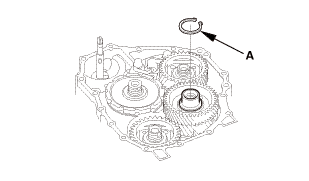
Remove the snap ring (A) securing the idler gear to the idler gear shaft.


11.

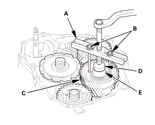
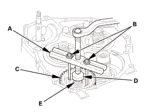
Install a puller (A) with two 6 x 1.0 mm bolts (B) on the idler gear shaft idler gear (C).


12.

Set a spacer (D) between the puller and the idler gear shaft (E).


13.

Remove the idler gear shaft idler gear.


14.

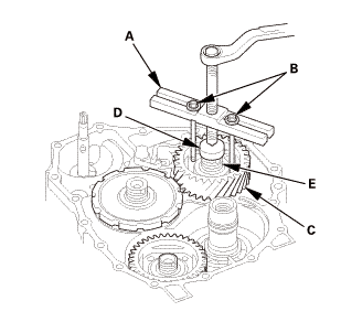
Install a puller (A) with two 6 x 1.0 mm bolts (B) on the mainshaft idler gear (C).


15.

Set a spacer (D) between the puller and the mainshaft (E).


16.

Remove the mainshaft idler gear.


17.

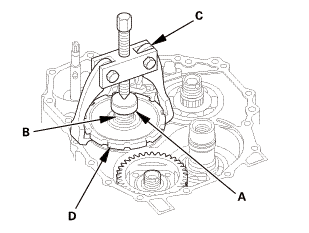
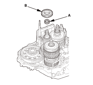
Place a spacer (A) on the countershaft (B).


18.

Set a commercially available bearing puller (C) on the park gear (D).


19.

Remove the park gear.


20.

Install a puller (A) with two 6 x 1.0 mm bolts (B) on the secondary shaft idler gear (C).


21.

Set a spacer (D) between the puller and the secondary shaft (E).


22.

Remove the secondary shaft idler gear.


15. A/T Transmission Housing


1.

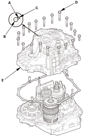
Align the spring pin (A) on the selector control shaft (B) with the transmission housing groove (C).


NOTE: Do not squeeze the end of the selector control shaft tips together when turning the control shaft.


2.

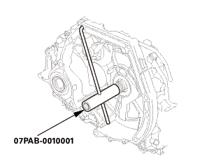
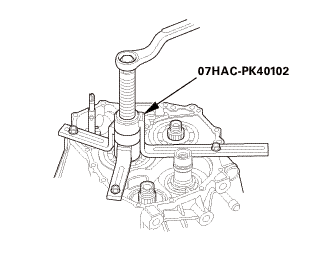
Install the housing puller over the countershaft.


NOTE: If the top arm of your housing puller is too short, replace it with 205 mm housing puller arm 07SAC-P0Z0101.


3.

Remove the transmission housing mounting bolts (D).


4.

Remove the transmission housing (E) using the housing puller.


16. A/T Reverse Idler Gear


1.

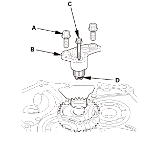
Remove the bolts (A) securing the reverse idler gear shaft holder (B).


2.

Install a 5 x 0.8 mm bolt (C) in the reverse gear shaft, and pull it to remove the reverse idler gear shaft (D) and the reverse idler gear shaft holder together.


3.

Remove the reverse idler gear (A).


17. A/T Mainshaft Bearing


1.

Expand the snap ring using snap ring pliers.


2.

Drive the mainshaft bearing out using the driver handle and the 72 x 75 mm bearing driver attachment.


NOTE: Do not remove the snap ring unless it is necessary to clean the groove in the transmission housing.


18. A/T Countershaft Reverse Gear


1.

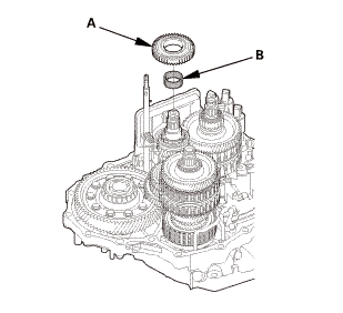
Remove the countershaft reverse gear (A).


2.

Remove the needle bearing (B).


19. Shift fork Shaft


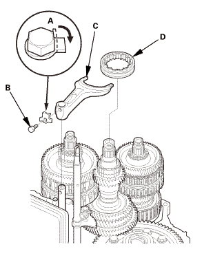
1.

Pry down the lock tab of the lock washer (A).


2.

Remove the lock bolt (B) and the lock washer.


3.

Remove the reverse shift fork (C) with the reverse selector (D) together.


20. A/T Mainshaft and Countershaft and Secondary Shaft Assembly

1.

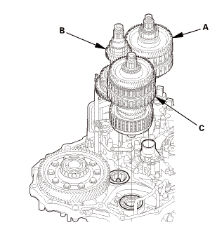
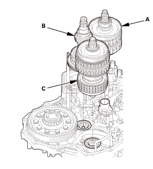
Remove the mainshaft subassembly (A), the countershaft subassembly (B), and the secondary shaft subassembly (C) together.


21. A/T Mainshaft

1.

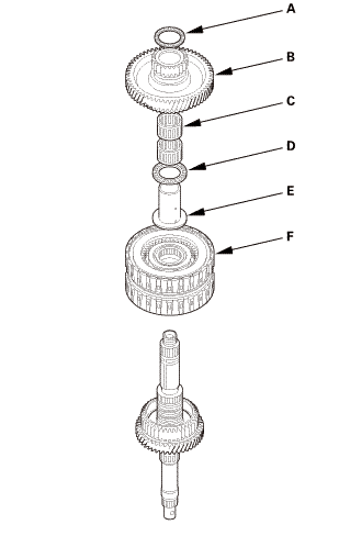
Remove the thrust needle bearing (A), 5th/reverse gear (B), the needle bearings (C), the thrust needle bearing (D), the 5th gear collar (E), and the 3rd/5th clutch (F).


2.

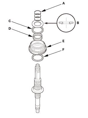
Remove the O-rings (A), the 40 x 63 mm thrust washer (B), the thrust needle bearing (C), the needle bearing (D), 3rd gear (E), and the thrust needle bearing (F).


3.

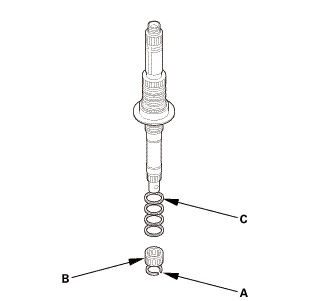
Remove the set ring (A), the needle bearing (B), and the sealing rings (C).


Inspection

1. Mainshaft - Inspection

1.

Inspect the thrust needle bearing and the needle bearing for galling and rough movement.


2.

Inspect the splines for excessive wear and damage.


3.

Check the shaft bearing surface for scoring and excessive wear.


2. 3rd Gear Axial Clearance - Inspection

22mmimm


1.

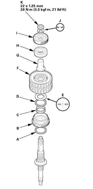
Install the thrust needle bearing (A), 3rd gear (B), the needle bearing (C), the thrust needle bearing (D), the 40 x 63 mm thrust washer (E), the 3rd/5th clutch (F), the 5th gear collar (G), and the transmission housing bearing (H)


NOTE: Do not install the O-rings during inspection.


2.

Install the idler gear (I) on the mainshaft by a press, then install the conical spring washer (J) and the locknut (K).


3.

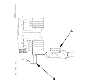
Set a dial indicator (A) on 3rd gear (B).


4.

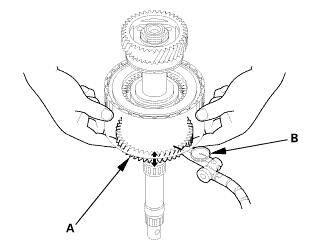
Lift 3rd gear (A) up while holding the mainshaft, and use the dial indicator (B) to read the 3rd gear axial clearance.


5.

Measure the 3rd gear axial clearance in at least three places while moving 3rd gear. Use the average as the actual clearance.


Standard: 0.04-0.10 mm (0.0016-0.0039 in)


6.

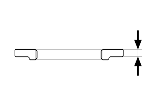
If the clearance is out of the standard, remove the 40 x 63 mm thrust washer, and measure its height.


7.

Select and install a new thrust washer, then recheck.


THRUST WASHER, 40 x 63 mm

No.

Height

1

3.750 mm (0.14764 in)

2

3.775 mm (0.14862 in)

3

3.800 mm (0.14961 in)

4

3.825 mm (0.15059 in)

5

3.850 mm (0.15157 in)

6

3.875 mm (0.15256 in)

7

3.900 mm (0.15354 in)

8

3.925 mm (0.15453 in)

9

3.950 mm (0.15551 in)

10

3.975 mm (0.15650 in)

11

4.000 mm (0.15748 in)


8.

After replacing the thrust washer, make sure the clearance is within the standard.


9.

Disassemble the installed parts from the mainshaft.


Reassembly

NOTE: Apply a light coat of clean ATF on all moving parts before reassembly.


1. A/T Mainshaft

1.

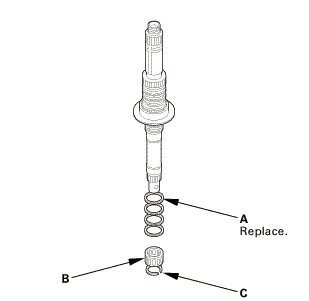
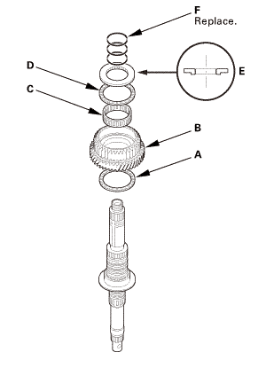
Install new sealing rings (A), the needle bearing (B), and the set ring (C).


2.

Install the thrust needle bearing (A), 3rd gear (B), the needle bearing (C), the thrust needle bearing (D), the selected 40 x 63 mm thrust washer (E), and new O-rings (F).


3.

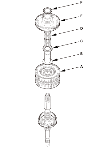
Install the 3rd/5th clutch (A), the 5th gear collar (B), the thrust needle bearing (C), the needle bearings (D), 5th/reverse gear (E), and the thrust needle bearing (F).


2. A/T Mainshaft and Countershaft and Secondary Shaft Assembly


1.

Assemble the mainshaft, the countershaft, and the secondary shaft.


2.

Join the mainshaft subassembly (A), the countershaft subassembly (B), and the secondary shaft subassembly (C) together, and install them.


3. Shift fork Shaft


1.

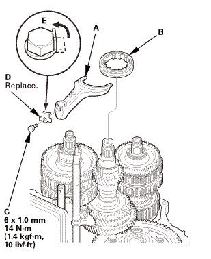
Install the reverse shift fork (A) with the reverse selector (B) together.


2.

Install the lock bolt (C) using a new lock washer (D).


3.

Bend the lock tab (E) of the lock washer against the bolt head.


4. A/T Countershaft Reverse Gear


1.

Install the needle bearing (A).


2.

Install the countershaft reverse gear (B).


5. A/T Mainshaft Bearing


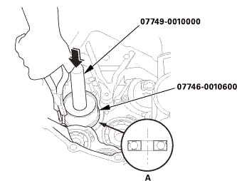
1.

Expand the snap ring using snap ring pliers.


2.

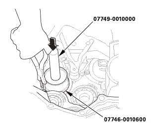
Install the mainshaft bearing (A) part-way into the housing using the driver handle and the 72 x 75 mm bearing driver attachment.


3.

Release the snap ring pliers, then push the bearing down into the transmission housing until the snap ring snaps in place around it.


6. A/T Reverse Idler Gear


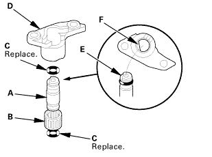
1.

Lightly coat the reverse idler gear shaft (A), the needle bearing (B), and new O-rings (C) with lithium grease.


2.

Assemble new O-rings and the needle bearing on the reverse idler gear shaft, then install the reverse idler gear shaft in the reverse idler gear shaft holder (D). Align the D-shaped (E) cut out of the shaft with the D-shaped area (F) of the holder.


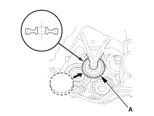
3.

Install the reverse idler gear (A) in the direction shown.


mm21inmk)

4.

Install the reverse idler gear shaft/holder assembly (A).


7. A/T Transmission Housing

1a1.2:mmmn!(4.:


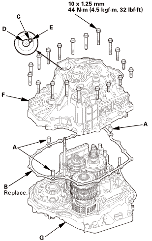
1.

Install the three dowel pins (A) and a new gasket (B).


2.

Align the spring pin (C) of the selector control shaft (D) with the transmission housing groove (E).


NOTE: Do not squeeze the end of the selector control shaft tips together when turning the shaft. If the tips are squeezed together, it will cause a faulty shift position signal or position due to the play between the selector control shaft and the transmission range switch.


3.

Place the transmission housing (F) on the torque converter housing (G).


NOTE: Do not install the input shaft (mainshaft) speed sensor and the output shaft (countershaft) speed sensor before installing the transmission housing.


4.

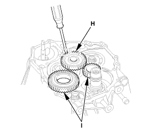
Wrap the tip of a screwdriver with tape so the reverse idler gear teeth do not get damaged. Engage the reverse idler gear (H) with the reverse gears (I) by rotating the idler gear using the screwdriver.


5.

Make sure the transmission housing is securely seated so there is no clearance between the transmission housing and the torque converter housing.


6.

Install and tighten the transmission housing mounting bolts in at least two steps, in a crisscross pattern.


8. End Cover Idler Gear Assembly

1.

Install the mainshaft holder onto the mainshaft.


2.

Lubricate the following parts with ATF:


Splines and threads of the mainshaft.

Splines of the mainshaft idler gear.

The old conical spring washer and the old locknut.


3.

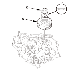
Install the mainshaft idler gear (A), the old conical spring washer (B), and the old locknut (C), and tighten the locknut to 216 N·m (22.0 kgf·m, 159 lbf·ft).


NOTE:

Do not tap the mainshaft idler gear to install.

Use a torque wrench to tighten the locknut. Do not use an impact wrench.


4.

Lubricate the following parts with ATF:


Splines and threads of the secondary shaft and the idler gear shaft.

Splines of the secondary shaft idler gear.

The old conical spring washer and the old locknut.


5.

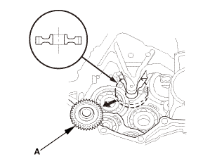
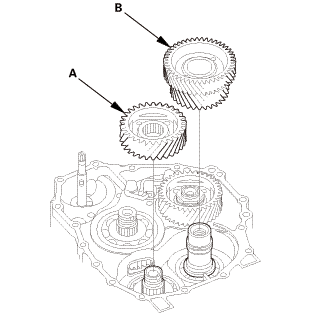
Install the secondary shaft idler gear (A).


NOTE: Do not tap the idler gear to install.


6.

Install the idler gear shaft idler gear (B).


NOTE: Do not tap the idler gear to install.


7.

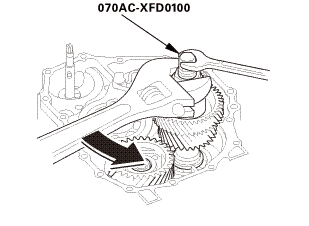
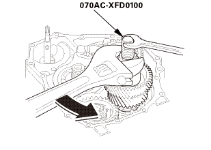
Set the gear installer set on the idler gear shaft and the idler gear.


8.

Tighten the installer nut to install the idler gear part-way.


NOTE: The installer nut has left-hand threads.


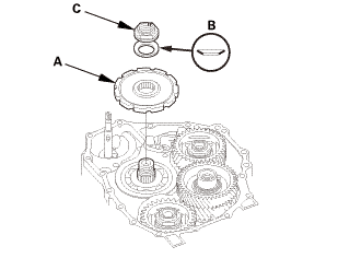
9.

Install the old conical spring washer (A) and the old locknut (B), and tighten the locknut to 225 N·m (23.0 kgf·m, 166 lbf·ft).


NOTE:

Do not tap the idler gears to install.

Use a torque wrench to tighten the locknut. Do not use an impact wrench.

Secondary shaft locknut has left-hand threads.


o7aacxfnmoa


10.

Retighten the installer nut to seat the idler gear in the idler gear shaft until it stops.


11.

Remove the gear installer set.


12.

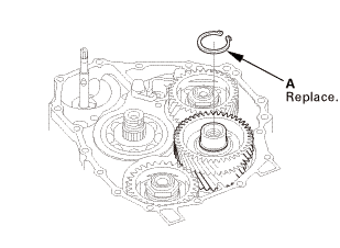
Install a new snap ring (A).


13.

Check that the snap ring is seated securely into the groove.


14.

Lubricate the following parts with ATF:


Splines and threads of the countershaft.

Splines of the park gear.

The old conical spring washer and the old locknut.


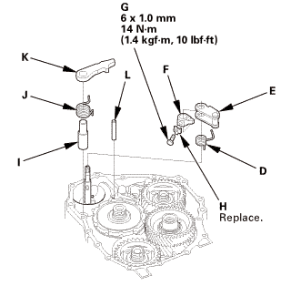
15.

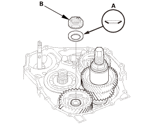
Install the park gear (A), the old conical spring washer (B), and the old locknut (C).


16.

Install the park lever spring (D), the park lever (E), and the park lever stop (F).


17.

Install the lock bolt (G) using a new lock washer (H).


NOTE: Do not bend the lock tab of the lock washer until inspect the park lever stop.


18.

Install the park pawl shaft (I), the park pawl spring (J), the park pawl (K), and the stop shaft (L).


19.

Lift the park pawl up, and engage it with the park gear, and tighten the locknut to 225 N·m (23.0 kgf·m, 166 lbf·ft).


NOTE:

Do not tap the park gear to install.

Use a torque wrench to tighten the locknut. Do not use an impact wrench.

Park gear locknut (countershaft locknut) has left-hand threads.


20.

Remove the old locknuts and the old conical spring washers from the mainshaft, the countershaft, and the secondary shaft.


21.

Lubricate the following parts with ATF:


Splines and threads of the mainshaft, the countershaft, and the secondary shaft.

New conical spring washers and new locknuts.

Areas where the conical spring washers contact the mainshaft idler gear, the secondary shaft idler gear, and the park gear.


22.

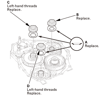
Install new conical spring washers (A) with facing stamped mark side up in the direction shown.


23.

Install a new mainshaft locknut (B), a new countershaft locknut (C), and a new secondary shaft locknut (D).


24.

Tighten the mainshaft locknut to 155 N·m (15.8 kgf·m, 114 lbf·ft).
Tighten the countershaft and secondary shaft locknuts to 167 N·m (17.0 kgf·m, 123 lbf·ft).


NOTE:

Use a torque wrench to tighten the locknut. Do not use an impact wrench.

The countershaft and secondary shaft locknuts have left-hand threads.


25.

Remove the mainshaft holder.


26.

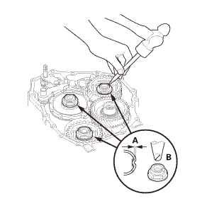
Stake the locknuts into the shafts to a depth (A) of 0.7-1.3 mm (0.027-0.051 in) using a 3.5 mm punch (B).


27.

Set the park lever in the P position.


28.

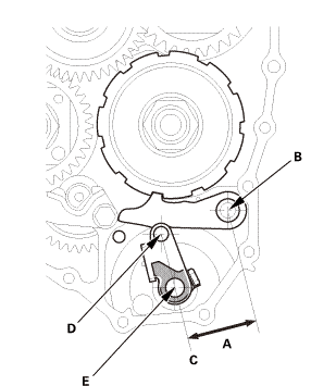
Measure the distance (A) between the park pawl shaft center (B) and the extension line (C) connected centers of the park lever roller pin (D) and the control shaft (E) in the vertical direction from the extension line.


Standard: 46.8-47.8 mm (1.843-1.882 in)


29.

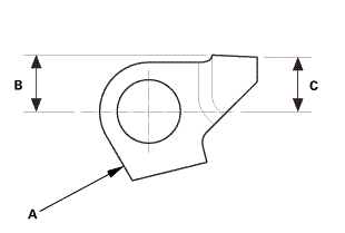
If the measurement is out of the standard, select and install the appropriate park lever stop (A) from the table.


PARK LEVER STOP

Mark

B

C

1

11.00 mm (0.4331 in)

11.00 mm (0.4331 in)

2

10.80 mm (0.4252 in)

10.65 mm (0.4193 in)

3

10.60 mm (0.4173 in)

10.30 mm (0.4055 in)


30.

After replacing the park lever stop, make sure the distance is within the tolerance.


31.

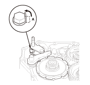
Bend the lock tab (A) of the lock washer against the bolt head.


9. ATF Pipe


1.

Install the 6 x 199 mm ATF pipe (A).


2.

Install the 8 x 192.5 mm ATF pipe (B).


3.

Install the 8 x 180.5 mm ATF pipes (C).


4.

Install the ATF lubrication pipe (D).


10. A/T Shift Solenoid Wire Harness - Reconnection

lve.l(camwur,

1.

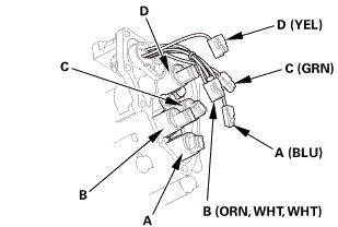
Connect the shift solenoid valve connectors:


BLU wire to shift solenoid valve A.

ORN, WHT, and WHT wires to shift solenoid valve B.

GRN wire to shift solenoid valve C.

YEL wire to shift solenoid valve D.


11. A/T Solenoid Cover

inmm

1.

Install the shift solenoid valve cover (A) with the dowel pins (B), a new gasket (C), and the clamp bracket (D).


12. ATF Filter Assembly

1.

Install the ATF inlet line/ATF hose/ATF filter assembly (A).


himm12mm


2.

Install the banjo bolt (B) using new sealing washers (C).


13. A/T Clutch Pressure Control Solenoid Valve B and C


1.

Clean the mounting surfaces and the fluid passages of the solenoid valve body and the transmission housing.


2.

Install a new gasket (A) with the blue side down and the white side up on the transmission housing.


3.

Install the 50 mm ATF pipe (D) and the ATF joint pipes (E).


4.

Install new O-rings (F) over the ATF joint pipes.


5.

Install A/T clutch pressure control solenoid valves B and C.


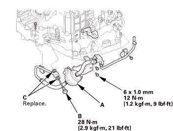
14. A/T Clutch Pressure Control Solenoid Valve A

mmi11


1.

Clean the mounting surfaces and the fluid passages of the solenoid valve body and the transmission housing.


2.

Install a new gasket (B) with the blue side down and the white side up on the transmission housing.


3.

Install the 35 mm ATF pipe (C) and the ATF joint pipes (D).


4.

Install new O-rings (E) over the ATF joint pipes.


5.

Install A/T clutch pressure control solenoid valve A.


15. Output Shaft (Countershaft) Speed Sensor (A/T)

1.

Install the output shaft (countershaft) speed sensor (A) using a new O-ring (B).


16. Input Shaft (Mainshaft) Speed Sensor

1.

Install the input shaft (mainshaft) speed sensor (A) using a new O-ring (B).


17. Transmission End Cover

mm12u....um,!mk)


1.

Install the dowel pins (A) and a new gasket (B).


2.

Install new O-rings (C) over the ATF pipes.


3.

Install the end cover (D).


18. ATF Warmer Bracket

mm27lhf!

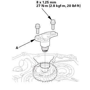
1.

Install the ATF warmer bracket (A).


19. Transmission Range Switch Subharness


1.

Install the clamp brackets (A).


2.

Install the transmission range switch subharness (B).


20. Transmission Range Switch

1.

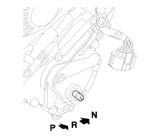
Make sure the selector control shaft is in the N position. If necessary, move the selector control shaft to the N position.


NOTE: Do not use the selector control shaft to adjust the shift position. If the selector control shaft tips are squeezed together it will cause a faulty signal or position due to play between the selector control shaft and switch.


2.

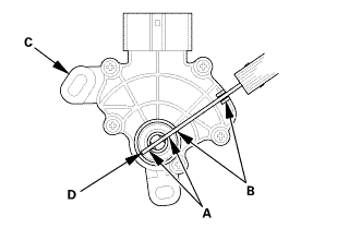
Align the cutouts (A) on the rotary-frame with the neutral positioning cutouts (B) on the transmission range switch (C), then put a 2.0 mm (0.079 in) feeler gauge blade (D) in the cutouts to hold the switch in the N position.


NOTE: Be sure to use a 2.0 mm (0.079 in) blade or equivalent to hold the switch in the N position.


3.

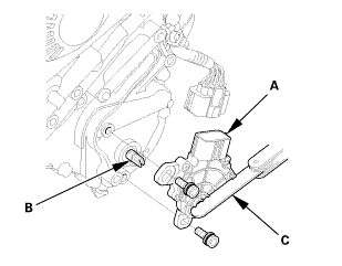
Install the transmission range switch (A) gently on the selector control shaft (B) while holding it in the N position with the 2.0 mm (0.079 in) blade (C).


4.

Tighten the bolts on the transmission range switch (A) while you continue holding the N position.


NOTE: Do not move the transmission range switch when tightening the bolts.


5.

Remove the feeler gauge (B).


6.

Check the connector (C) for corrosion, dirt, or oil, and clean or repair if necessary, then connect the connector securely.


21. Transmission Range Switch Cover

mmnm

1.

Install the transmission range switch cover (A).


A/T Housing Countershaft Bearing Replacement (A/T)
Removal 1. Transmission Range Switch Cover 1. Remove the transmission range switch cover (A). ...

ATF Temperature Sensor Removal and Installation (A/T)
7371J4 1. Vehicle Lift 1. Raise the vehicle on a lift, and make sure it is securely supported. ...
See also:

Honda Civic Owners Manual. Inspecting and Changing Fuses
Turn the ignition switch to LOCK 0*1. Turn headlights and all accessories off.  Remove the fuse box cover.  Check the large fuse in the engine compartment. ► If the fuse is blown, use a Phillips-head screwdriver to remove the screw and replace it with a new one. ...

© 2016-2024 Copyright www.hocivic.com

0.0287