Honda Civic Service Manual: Valve Clearance Adjustment (K24Z7)
1103A3

Removal
|
|
|
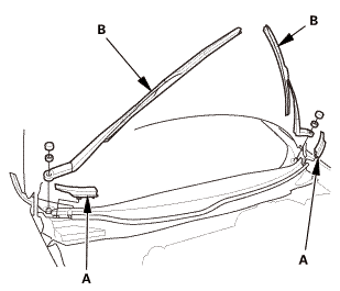
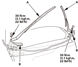
NOTE: Set the wiper arms to the auto-stop position before removal.
|
|
1.
|
Remove the cowl top wiper covers (A).
|
|
2.
|
Remove the wiper arms (B).
|
|
|
|
|
1.
|
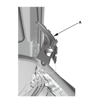
Remove the side cowl cover (A).
|
|
2.
|
The left side is shown; repeat on the right side.
|
|
|

|
|
1.
|
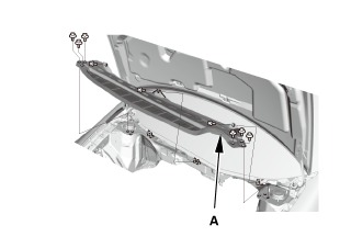
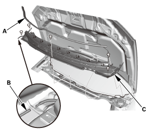
Remove the center cowl cover (A).
|
|
2.
|
Disconnect the windshield washer tube (B).
|
|
3.
|
If necessary, remove the hood rear seal (C).
|
|
|
|
|
1.
|
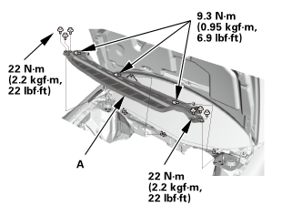
Remove the under cowl panel (A).
|
|
|
|
|
1.
|
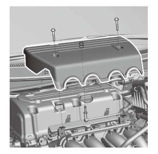
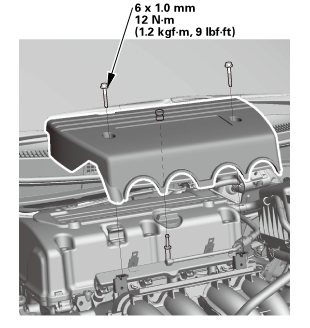
Remove the engine cover.
|
|
|
|
|
1.
|
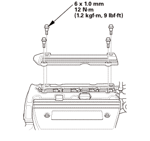
Remove the ignition coil cover.
|
|
|
|
|
1.
|
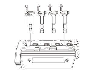
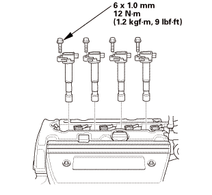
Remove the ignition coils.
|
|
|
|
|
1.
|
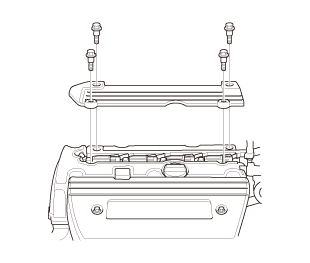
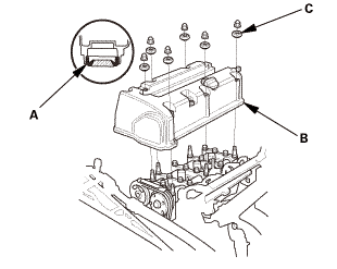
Remove the cylinder head cover.
|
|
 Adjustment
|
NOTE: Connect the HDS to the DLC and monitor ECT SENSOR 1 with the HDS.
Adjust the valve clearance only when the engine coolant temperature is less
than 100 °F (38 °C).
|
| 1. |
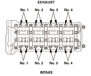
Valve Clearance - Adjustment |
|
|
|
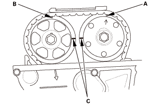
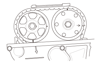
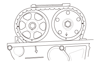
1.
|
Set the No. 1 piston at top dead center (TDC). The punch mark
(A) on the VTC actuator and the punch mark (B) on the exhaust camshaft
sprocket should be at the top. Align the TDC marks (C) on the VTC
actuator and the exhaust camshaft sprocket.
|
|
|
2.
|
Select the correct feeler gauge for the valve clearance you are going
to check.
|
|
|
Valve Clearance
|
|
Intake:
|
0.21-0.25 mm (0.009-0.009 in)
|
|
Exhaust:
|
0.25-0.29 mm (0.010-0.011 in)
|
|
|
|
|
|
|
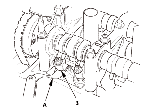
3.
|
Insert the feeler gauge (A) between the adjusting screw (B) and
the end of the valve stem on the No.1 cylinder, and slide it back
and forth; you should feel a slight amount of drag.
|
|
|
|
|
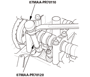
4.
|
If you feel too much or too little drag, loosen the locknut with
the locknut wrench and the adjuster, and turn the adjusting screw
until the drag on the feeler gauge is correct.
|
|
5.
|
Tighten the locknut to the specified torque, and recheck the
clearance. Repeat the adjustment if necessary.
|
|
|
Specified Torque
|
|
7 x 0.75 mm
|
|
14 N·m (1.4 kgf·m, 10 lbf·ft)
|
|
Apply new engine oil to the nut threads.
|
|
|
|
|
|
|
|
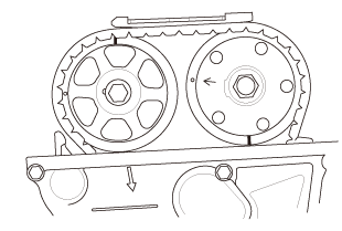
6.
|
Rotate the crankshaft 180 ° clockwise (camshaft pulley turns
90 °).
|
|
7.
|
Check and, if necessary, adjust the valve clearance on the No.
3 cylinder.
|
|
|
|
|
8.
|
Rotate the crankshaft 180 ° clockwise (camshaft pulley turns
90 °).
|
|
9.
|
Check and, if necessary, adjust the valve clearance on the No.
4 cylinder.
|
|
|
|
|
10.
|
Rotate the crankshaft 180 ° clockwise (camshaft pulley turns
90 °).
|
|
11.
|
Check and, if necessary, adjust the valve clearance on the No.
2 cylinder.
|
|

Installation
|
|
|
1.
|
Check the spark plug seals for damage. If any seals are damaged,
replace them.
|
|
2.
|
Thoroughly clean the head cover gasket and the groove.
|
|
NOTE: Check and, if necessary, replace the head cover gasket.
|
|
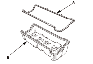
3.
|
Install the head cover gasket (A) in the groove of the cylinder
head cover (B). Make sure the head cover gasket is seated securely.
|
|
|
|
|
4.
|
Remove all of the old liquid gasket from the chain case and the
No.5 rocker shaft holder.
|
|
5.
|
Clean the head cover contacting surfaces with a shop towel.
|
|
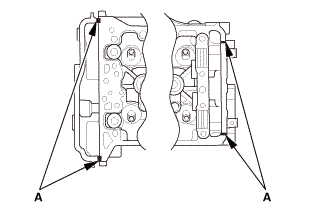
6.
|
Apply liquid gasket, (P/N 08718-0004 or 08718-0009) on the chain
case and the No. 5 rocker shaft holder mating areas (A). Install
the component within 5 minutes of applying the liquid gasket.
|
|
NOTE: If too much time has passed after applying the liquid gasket,
remove the old liquid gasket and residue, then reapply new liquid
gasket.
|
|
|
|
|
7.
|
Set the spark plug seals (A) on the spark plug tubes. Place the
cylinder head cover (B) on the cylinder head, then slide the cover
slightly back and forth to seat the head cover gasket.
|
|
8.
|
Inspect the spark plug seals for damage.
|
|
9.
|
Inspect the cover washers (C). Replace any washer that is damaged
or deteriorated.
|
|
|
|
|
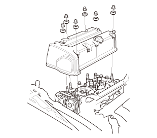
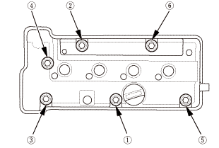
10.
|
Tighten the bolts in two steps. In the final step torque bolts,
in sequence, to 12 N·m (1.2 kgf·m, 9 lbf·ft).
|
|
NOTE:
|
|

|
Wait at least 30 minutes before filling the engine
with oil.
|
|
|
|
Do not run the engine for at least 3 hours after
installing the head cover.
|
|
|
|
|
|
|
1.
|
Install the ignition coils.
|
|
|
|
|
1.
|
Install the ignition coil cover.
|
|
|
|
|
1.
|
Install the engine cover.
|
|
|
|
|
1.
|
Install the side cowl cover (A).
|
|
2.
|
The left side is shown; repeat on the right side.
|
|
|
|
|
1.
|
If necessary, install the hood rear seal (A).
|
|
2.
|
Connect the windshield washer tube (B).
|
|
3.
|
Install the center cowl cover (C).
|
|
|
 22mm)2222 22mm)2222
|
|
1.
|
Install the under cowl panel (A).
|
|
|
 1.122 1.122
|
|
NOTE: Set the wiper arms to the auto-stop position before installation.
|
|
1.
|
Install the wiper arms (A).
|
|
2.
|
Install the cowl top wiper covers (B).
|
|
1103A3
1.
Engine Cover
1.
Remove the engine cover.
2.
Cylinder Head Co ...
1.
Fuel Pressure - Relieving (Between the engine and the manual shut-off
valve) (Natural Gas Model)
Compressed natural gas is flammable ...
 Valve Clearance Adjustment (Except K24Z7)
 Valve Inspection (R18A9)