Honda Civic Service Manual: Synchro Sleeve and Hub Disassembly, Reassembly, and Inspection (K24Z7)
 Disassembly
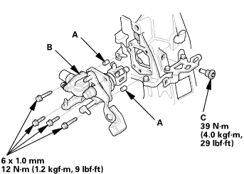
| 1. | M/T Change Lever Assembly |
|
|
|
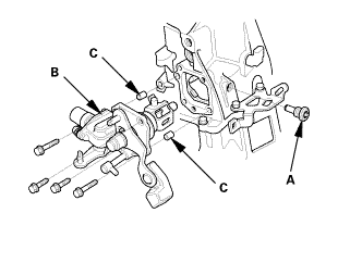
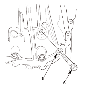
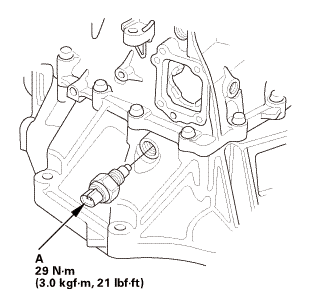
| 2. | Back-Up Light Switch |
|
|
|
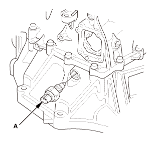
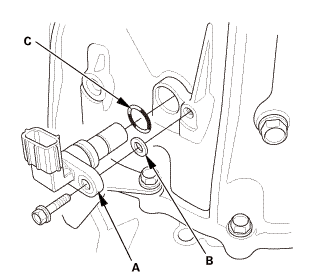
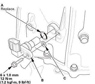
| 3. | Output Shaft (Countershaft) Speed Sensor |
|
|
|
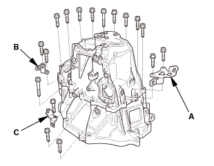
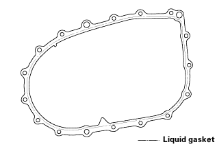
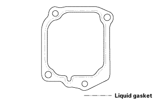
| 4. | Transmission Housing |
|
|
|
|
|
|
|
|
|
|
|
|
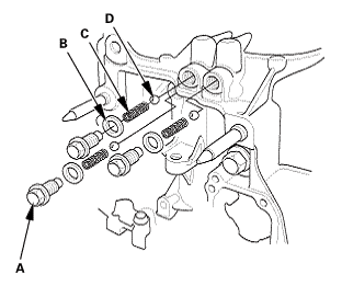
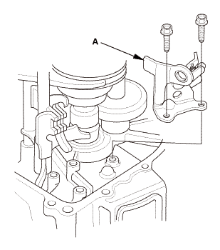
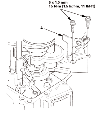
| 5. | Reverse Shift Fork |
|
|
|
| 6. | Baffle Plate |
|
|
|
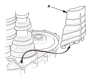
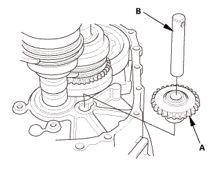
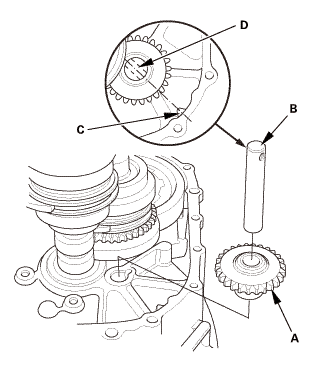
| 7. | Reverse Idler Gear |
|
|
|
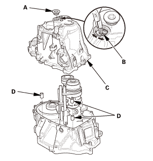
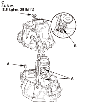
| 8. | M/T Mainshaft and Countershaft and Shift Fork Assembly |
|
|
|
|||||||||||||||
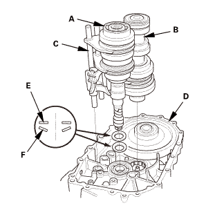
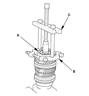
| 9. | M/T Mainshaft 5th and 6th Gear |
|
|
|
|
|
|
|||||||||
| 10. | M/T Mainshaft 3rd and 4th Gear |
|
|
|
|||||||||
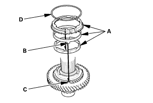
| 11. | M/T Countershaft |
|
|
|
|
|
|
|
|
|
|
|
|
 Inspection
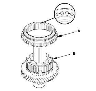
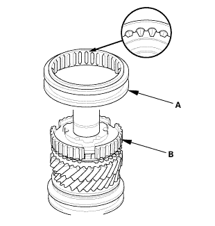
| 1. | Synchro Sleeve and Hub Inspection |
|
|
|
||||||||||||||||||||

 Reassembly
| 1. | M/T Countershaft |
|
|
|
|
|
|
|
|
|
|
|
|
|||||||||
|
|
|
|
|
|
|
|
|
|
|
|
|||||||||
 sun
sun|
|
|
||||||
 s,m
s,m|
|
|
||||||
 (2,snn
|
|
|
||||||
 zs,4ioums.uuau1uu
|
|
|
||||||||||||||||||||
 nms.nn:mnn
|
|
|
||||||||||||||||||||||||||||||||||||||||||||||||||||||||||||||||||||||||||||||
|
|
|
|
|
|
||||||
|
|
|
|||||||||||||||
 nms.nu:n1nn
|
|
|
|||||||||
 mm(noumn
| 2. | M/T Mainshaft 3rd and 4th Gear |
|
|
|
|
|
|
|
|
|
||||||
|
|
|
|
|
|
|
|
|
|
|
|
| 3. | M/T Mainshaft 5th and 6th Gear |
|
|
|
|
|
|
|
|
|
|
|
|
|||||||||
|
|
|
|
|
|
| 4. | M/T Mainshaft and Countershaft and Shift Fork Assembly |
|
|
|
||||||||||||||||||
| 5. | Reverse Idler Gear |
|
|
|
| 6. | Baffle Plate |
|
|
|
| 7. | Reverse Shift Fork |
|
|
|
 mmlbf!
| 8. | Transmission Housing |
|
|
|
||||||||||||||||||||
|
|
|
|||||||||||||||
|
|
|
|||||||||||||||||||||||
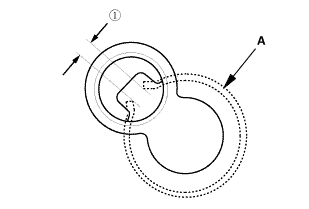
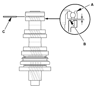
 as installed:
3.3-6.0 mm (0.130-0.236 in)
as installed:
3.3-6.0 mm (0.130-0.236 in)|
|
|
|
|
|
||||||||||
|
|
|
|
|
|
| 9. | Output Shaft (Countershaft) Speed Sensor |
|
|
|
| 10. | Back-Up Light Switch |
|
|
|
| 11. | M/T Change Lever Assembly |
|
|
|
||||||||||||||||||||
 iukn
iukn|
|
|
 Synchro Ring and Gear Inspection (R18Z1 M/T)
Removal
1.
M/T Change Lever Assembly
1.
Remove the change lever assembly (A).
...
See also:
Honda Civic Owners Manual. Protecting Infants
An infant must be properly restrained in a rear-facing, reclining child seat
until the
infant reaches the seat manufacturer’s weight or height limit for the seat, and
the
infant is at least one year old. Many experts recommend use of a rear-facing
seat for
a child up to two years old if t ...
